- Digital read out
-
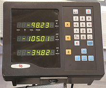
A digital read out (DRO) is a small computer (display unit) usually with an integrated keyboard and some means of numeric representation. It reads the signals generated by the linear encoder (or less frequently by rotary encoders) installed to several machine's axes used to keep track of workpiece position (milling and the like) or the tool's position (lathes and grinders). In the shop argot this complete system conformed by the computer and the encoders are referred to simply as DRO. Such a system is commonly fitted to most machines in today's shops: lathes, cylindrical grinders, milling machines, surface grinders, boring mills and other machine tools to allow the operator to work faster and with greater accuracy. The use of DROs are not limited to manual equipment as CNC equipment can usually be switched to manual operation and in this case a form of DRO is simulated on the Control Panel of a robotic machine.
Contents
Display unit (computer)
Several 7-segment displays, or an LCD screen on more expensive models display the current position of each machine axes. Such as X, Y, Z for a common milling machines and those plus U and W for highly sophisticated 5 axes vertical machining centers; x and z for a lathes or cylindrical grinders; and just z for a surface grinder.
Common Standard functions on a modern DRO
Modern DROs have a lot of functionality, giving you finger tip control over the most frequent shop operations. The following were taken from a popular brand User's manual:
- Imperial (inch) and metric interchange.
- The so called "1/2" function. It takes the current value of an axis and divides it by two. It is used to find the accurate center of a workpiece or an existing feature such as a hole.
- Preset dimensions. The operator can type in the value of an axis. Used to locate a feature by using an edge finder.
- Absolute or Incremental modes. The position of a feature given on a blue print is given by one of two methods:
- Absolute, which means the coordinate is relative to the part's absolute zero (usually one of its corners or its center).
- Relative, meaning the coordinate is referred to some other feature, usually the last one machined.
- Bolt holes. The drilling or boring of several holes along an arch without using a rotary table.
- Inclines, compute a cut across an incline.
- Memory, Stores hundreds or thousands of points.
- Scientific calculator. A full featured calculator has been integrated to some select models.
Linear encoders
All encoders have a scale that attaches to the moving part (the table, carriage, knee or quill) and a reader that attaches to the part that does not move. All are subject to damage from impact, so should be protected with some sort of metallic shield.
Glass scales
Made from strips of high quality glass with evenly etched marks just like the marks of a ruler, but very small (the smallest are just 5 μm apart). Two optical sensors (phototransistors or photodiodes) are placed very close to each other to make a linear encoder . When the machine axis moves, the dark marks move under the optical encoders triggering them in succession. If movement is from, for example, left to right, encoder A is triggered first and encoder B afterwards. So the computer can know that the scale moved 5μm to the right. And, if encoder B triggers first and A does as follow the computer knows it was in the other direction.
Commercial models are enclosed in an aluminum "box" with a rubber protection on the side where the encoder slides. Used primarily where shielding from coolant and chips is necessary or where a resolution of 5μm (0.0002 in) or better is required (surface grinders).
Glass scales used to be too expensive for home use, but have recently fallen in price (late 2008) to where they are competitive with the other technologies.
Electronic scales
Instead of glass, a printed circuit on a stainless steel ruler is used to trigger at least two microelectronic hall effect sensors. Resolution is limited to 0.01mm (0.0005 in) but shielding from coolant and flying chip is not a requirement. These scales are very resistant to everyday shop contaminants and debris. Electronic scales are much cheaper than their glass counterparts.
Electronic scales are available with build in displays so they can be used independently.
Ball scales
The ball scales produced by Newall use an electromagnetic field to track ball bearings in a tube. They sell under the trade name Spherosyn and Microsyn. They work only with Newall DROs.
Rack and Gear scales
These models use a rack (toothed metal strip) that meshes with a gear that turns a rotary encoder. Claimed accuracy of .002 inches per foot, though users frequently report it Is much more accurate, with no measurable deviation over several feet of travel. Debris getting between the gear and rack is a concern.
Quill DRO
Vertical Quill DRO
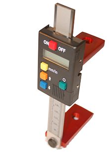
This is a speciality DRO system composed of a computer and an electronic scale in one small piece of equipment. Usually battery operated. Installed on the quill of a milling machine (whence its name). At this part of the machine coolant splash, flying chip and accidental shock are day-to-day events, therefore it is a very bad place for a glass scale used in conventional DROs. It also gives the operator a lot of comfort by being placed right in front of his eyes next to the controls that adjust the machine and it has not a single wire that can get trapped in the cluttered quill area. A very common setup is to have a regular DRO with glass scales on the milling machine's table and a separate vertical quill DRO. This gives a resolution of 0.005mm to the table position and 0.01mm to the quill. Both exceed by far the expected "0.04mm accuracy of the milling process" (The Machinery's Handbook)
Horizontal quill DRO
It is very much like the vertical version, except in that it is designed to be installed in a horizontal position. The only difference is the orientation of the display and the buttons to be seen and operated horizontally. This device is not for standard shop equipment. It is used in research and calibration of other equipment.
References
OBERG et al., The Machinery's Hand Book. 26th edition, Industrial Press, New York, 2000. p. 630.
Categories:
Wikimedia Foundation. 2010.


