- Ethernet crossover cable
-
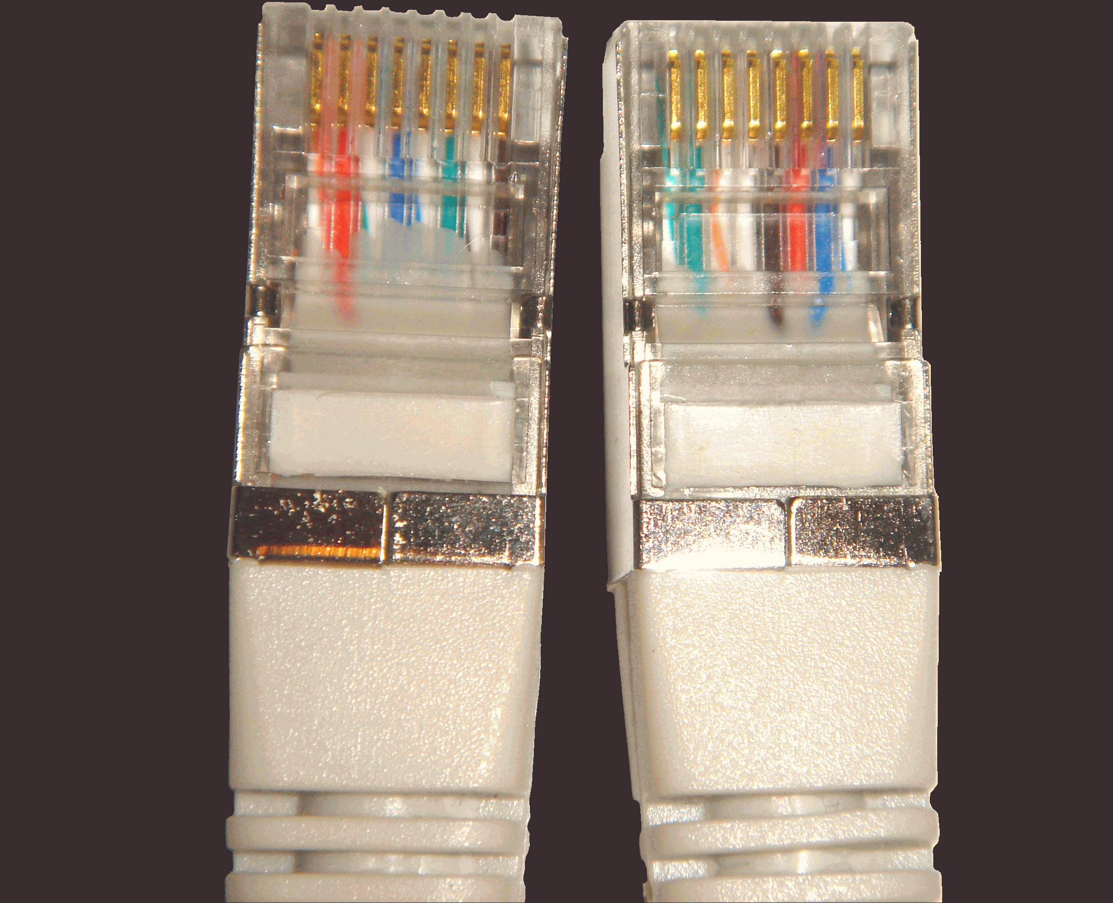
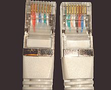 Gigabit T568B crossover cable ends
An Ethernet crossover cable is a type of Ethernet cable used to connect computing devices together directly. Normal straight through or patch cables were used to connect from a host network interface controller (a computer or similar device) to a network switch, hub or router. A cable with connections that "cross over" was used to connect two devices of the same type: two hosts or two switches to each other. Owing to the inclusion of Auto-MDIX capability, modern implementations of the Ethernet over twisted pair standards usually no longer require the use of crossover cables.
Contents
Overview
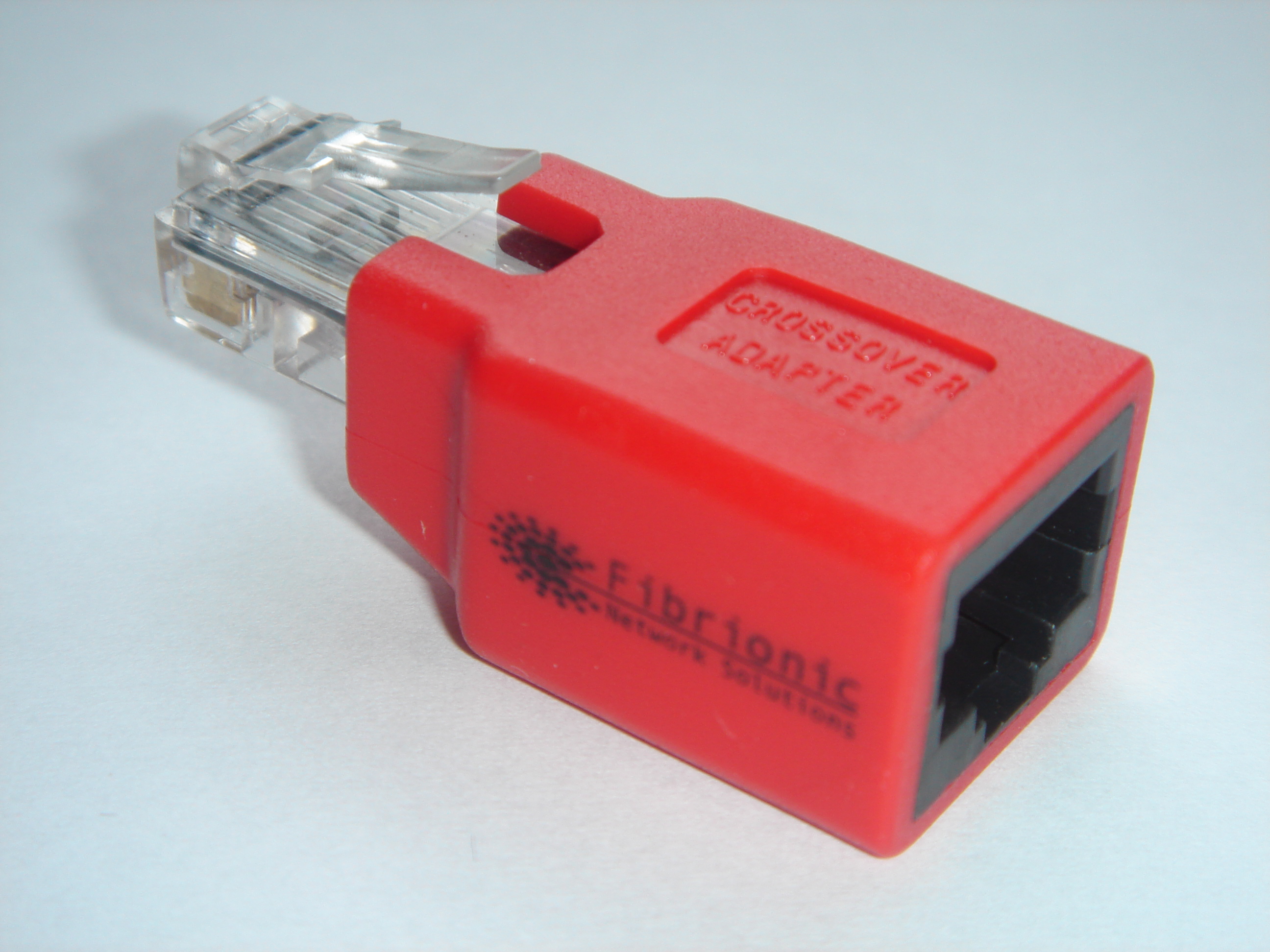
 8P8C modular crossover adapter
The 10BASE-T and 100BASE-TX Ethernet standards use one wire pair for transmission in each direction. By convention, one wire of the pair is designated "+" and the other "-". Following traditional telephone terminology, the + signal from each pair connects to the tip conductor, and the - signal is connected to the ring conductor. This requires that the transmit pair of each device be connected to the receive pair of the device on the other end. When a terminal device is connected to a switch or hub, this crossover is done internally in the switch or hub. A standard straight through cable is used for this purpose where each pin of the connector on one end is connected to the corresponding pin on the other connector.
One network interface controller may be connected directly to another without the use of a switch or hub, but in that case the crossover must be done externally in the cable or modular crossover adapter in a manner similar to how the null modem was used to directly connect two teleprinters. Since 10BASE-T and 100BASE-TX use pairs 2 and 3, these two pairs must be swapped in the cable. This is a crossover cable. A crossover cable was also used to connect two hubs or two switches on their upstream ports .
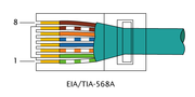
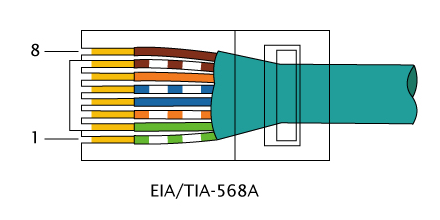
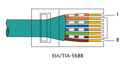
Because the only difference between the T568A and T568B pin/pair assignments are that pairs 2 and 3 are swapped, a crossover cable may be envisioned as a cable with one modular connector following T568A and the other T568B (see Jack crossover wiring). Such a cable will work for 10BASE-T or 100BASE-TX. Gigabit Ethernet (and an early Fast Ethernet variant, 100BASE-T4) use all four pairs and also requires the other two pairs (1 and 4) to be swapped. This meant common crossover cables available in the retail market were usually not compatible with the Gigabit Ethernet convention, but newer crossover cables could be made that worked for all speeds. The polarity of each pair is not swapped, but the pairs crossed as a unit: the two wires within each pair are not crossed.[1]
Crossover cable pinouts
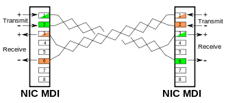 Crossover cable connecting two MDI ports
In practice, it does not matter if non-crossover Ethernet cables are wired as T568A or T568B, just so long as both ends follow the same wiring format. Typical commercially available "pre-wired" cables can follow either format depending the manufacturer. What this means is that one manufacturer's cables are wired one way and another's the other way, yet both are correct and will work. In either case, T568A or T568B, a normal (un-crossed) cable will have both ends wired according to the layout in the Connection 1 column.
Although the Gigabit crossover is defined in the Gigabit Ethernet standard[2], in practice all Gigabit PHYs feature an auto-MDIX capability and are designed for compatibility with the existing 100BASE-TX crossovers. The IEEE-specified Gigabit crossover is generally seen as unnecessary.
Certain equipment or installations, including those in which phone and/or power are mixed with data in the same cable, may require that the "non-data" pairs 1 and 4 (pins 4, 5, 7 and 8) remain un-crossed.
Two pairs crossed, two pairs uncrossed
10BASE-T or 100BASE-TX crossoverPin Connection 1: T568A
Connection 2: T568B

Pins on plug face signal pair color signal pair color 1 BI_DA+ 3 
white/green stripeBI_DB+ 2 
white/orange stripe
2 BI_DA- 3 
green solidBI_DB- 2 
orange solid3 BI_DB+ 2
white/orange stripeBI_DA+ 3
white/green stripe4 1 
blue solid1
blue solid5 1 
white/blue stripe1
white/blue stripe6 BI_DB- 2
orange solidBI_DA- 3
green solid7 4 
white/brown stripe4
white/brown stripe8 4 
brown solid4
brown solidGigabit T568A crossover
All four pairs crossed
10BASE-T, 100BASE-TX, 100BASE-T4 or 1000BASE-T crossover (shown as T568A)Pin Connection 1: T568A Connection 2: T568A Crossed Pins on plug face signal pair color signal pair color 1 BI_DA+ 3
white/green stripeBI_DB+ 2
white/orange stripe2 BI_DA- 3
green solidBI_DB- 2
orange solid3 BI_DB+ 2
white/orange stripeBI_DA+ 3
white/green stripe4 BI_DC+ 1
blue solidBI_DD+ 4
white/brown stripe5 BI_DC- 1
white/blue stripeBI_DD- 4
brown solid6 BI_DB- 2
orange solidBI_DA- 3
green solid7 BI_DD+ 4
white/brown stripeBI_DC+ 1
blue solid8 BI_DD- 4
brown solidBI_DC- 1
white/blue stripeGigabit T568B crossover
All four pairs crossed
10BASE-T, 100BASE-TX, 100BASE-T4 or 1000BASE-T crossover (shown as T568B)Pin Connection 1: T568B Connection 2: T568B Crossed Pins on plug face signal pair color signal pair color 1 BI_DA+ 2
white/orange stripeBI_DB+ 3
white/green stripe2 BI_DA- 2
orange solidBI_DB- 3
green solid3 BI_DB+ 3
white/green stripeBI_DA+ 2
white/orange stripe4 BI_DC+ 1
blue solidBI_DD+ 4
white/brown stripe5 BI_DC- 1
white/blue stripeBI_DD- 4
brown solid6 BI_DB- 3
green solidBI_DA- 2
orange solid7 BI_DD+ 4
white/brown stripeBI_DC+ 1
blue solid8 BI_DD- 4
brown solidBI_DC- 1
white/blue stripeAutomatic crossover
Main article: Auto-MDIXIf one of two connected devices has the automatic MDI/MDI-X configuration feature there is no need for crossover cables. Introduced in 1998, this made the distinction between uplink and normal ports and manual selector switches on older hubs and switches obsolete.[3]
Although Auto-MDIX was specified as an optional feature in the 1000BASE-T standard[2], in practice it is implemented widely on most interfaces. It has been available for example on Apple Inc. computers since about the Power Mac G5.[4]
Besides the eventually agreed upon Automatic MDI/MDI-X, this feature may also be referred to by various vendor-specific terms including: Auto uplink and trade, Universal Cable Recognition and Auto Sensing.
See also
- Crossover cable
- Jack crossover wiring
- Registered jack, which expands on the introduction and evolution of these connectors.
References
- ^ Charles E. Spurgeon (2000). Ethernet: the Definitive Guide. O'Reilly Media. p. 247. ISBN 9781565926608. http://books.google.com/books?id=MRChaUQr0Q0C&pg=PA247.
- ^ a b Clause "40.4.4 Automatic MDI/MDI-X Configuration" in IEEE 802.3-2008: ("IEEE 802.3-2008, Part 3". 2010-06-22. p. 192. http://standards.ieee.org/getieee802/download/802.3-2008_section3.pdf. Retrieved 2011-02-07. "Implementation of an automatic MDI/MDI-X configuration is optional for 1000BASE-T devices.")
- ^ Daniel Dove (February 1998). 802.3 "1000BASE-T Automatic Crossover Algorithm". Presentation to IEEE 802.3ab working group. http://www.ieee802.org/3/ab/public/feb98/ddmdix1.pdf 802.3. Retrieved June 17, 2011.
- ^ "Apple products that require and Ethernet cable". Apple support web site. October 22, 2008. http://support.apple.com/kb/HT2274/. Retrieved June 17, 2011.
External links
Ethernet family of local area network technologies Speeds 10 Mbits/sec: (10BASE5, 10BASE2, 10BASE-T) • 100 Mbits/sec • Gigabit/sec • 10 Gigabits/sec • 100 Gigabits/sec • Terabit/secGeneral Historic Applications Transceivers Interfaces Categories:- Ethernet cables
- Signal cables

Wikimedia Foundation. 2010.