- Tower Mounted Amplifier
-
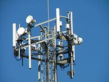 Crowded mast with TMAs (white rectangular boxes) mounted behind all the panel (rectangular) antennas
A Tower Mounted Amplifier or Mast Head Amplifier is a Low-noise amplifier (LNA) mounted as close as practical to the antenna in mobile masts or Base Transceiver Stations. A TMA reduces the base transceiver station noise figure (NF) and therefore improve its overall sensitivity; in other words the mobile mast is able to receive weaker signals.
Contents
Benefits in mobile communications
In two way communications systems, there are occasions when one way, one link, is weaker than the other, normally referenced as unbalanced links. This can be fixed by making the transmitter on that link stronger or the receiver more sensitive to weaker signals.
TMAs are used in mobile networks to improve the sensitivity of the uplink in mobile phone masts. Since the transmitter is a mobile phone it cannot be easily modified to transmit stronger signals. Improving the uplink translates into a combination of better coverage and mobile transmitting at less power, which in turn implies a lower drain from its batteries, thus a longer battery charge.[1]
There are occasions when the cable between the antenna and the receiver is so lossy (too thin or too long) that the signal weakens from the antenna before reaching the receiver; therefore it may be decided to install TMAs from the start to make the system viable. In other words, the TMA can only partially correct, or palliate, the link imbalance.
Drawbacks/pitfalls
- If the received signal is not weak, installing a TMA will not deliver its intended benefit.
- If the received signal is strong enough, it may cause the TMA to create its own interference which is passed on to the receiver.[2]
- In some mobile networks (e.g. IS-95 or WCDMA - aka European 3G -), it is not simple to detect and correct unbalanced links since the link balance is not constant; link balance changes with traffic load. However, other mobile networks (e.g. GSM) have a constant link, therefore it is possible analyse call records and establish where TMAs are needed.[1]
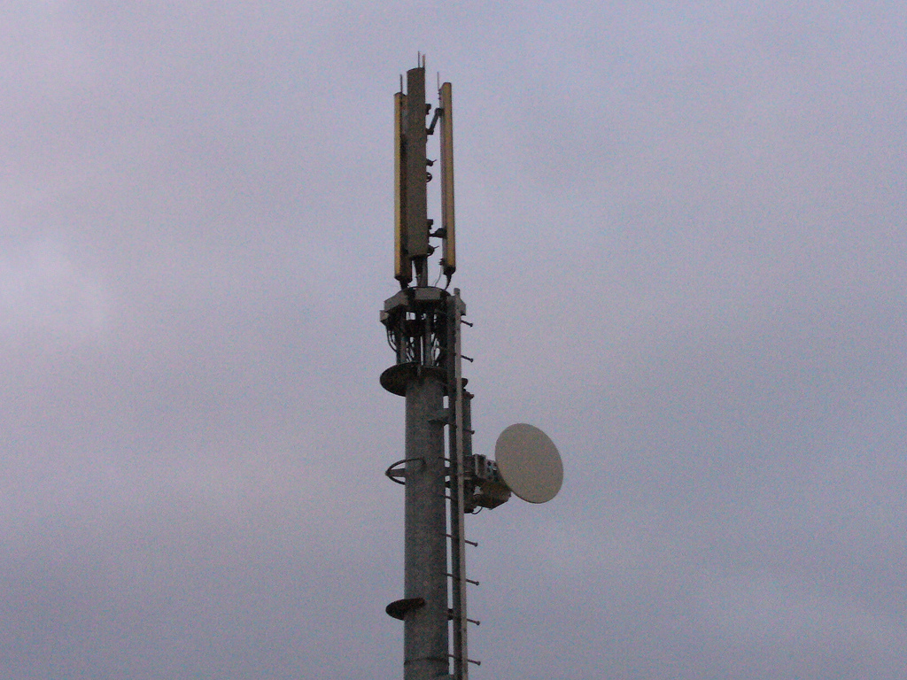
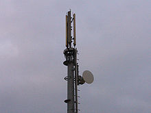 Simple phone mast with three TMAs (horizontal rectangular boxes) visible at the top of metal tower and before rectangular antennas
- There might be practical room restrictions, visual, or structural weight restrictions to install a TMA at the top of a phone mast.
- If the TMA fails, it may render the system unusable until serviced, unless it can be bypassed.
- Servicing TMAs is harder than servicing receivers - and thus more expensive - as the TMA may be dangerously near (near field) of the antenna and high up in a tower. The receiver may alternatively be housed in a cabinet or hut at the base of the tower.[3][4]
Mathematical principles
In a receiver, the receiving path starts with the signal originating at the antenna. Then the signal is amplified in further stages within the receiver. It is actually not amplified all at once but in stages, with some stages producing other changes (like changing the signal's frequency).
The principle can be demonstrated mathematically; the receiver's noise figure is calculated by modularly assessing each amplifier stage. Each stage consists of a noise figure (F) and an amount of amplification, or gain (G). So amplifier number 1 will be right after the antenna and described by F1 and G1. The relationship of the stages is known as the Friis formula.

Note that:
- The first amplifier will set the temperature (F1); nothing reduces its contribution to the total.
- The second amplifier's temperature (F2) will also influence the total but it is reduced (divided) by the gain of the first amplifier G1.
- The third amplifier's temperature is influencing even less, as it is reduced by its preceding amplifier gains G1, G2.
- And so on until N stages.[5][6]
Applying the Friis formula to TMAs
Typical receiver without TMA
Start with a typical receiver: Antenna - Connecting Cable (stage 1) - Receiver (stage 2).

The first stage after the antenna is actually the connecting cable. Therefore:
- Stage 1: F1 is equal to the loss of the cable and will increase with ambient temperature [7]
- Stage 2: G1 will depend on the lossiness of the cable. Since the element is lossy G1 is less than one; in order words, it will increase F2 − 1. The more loss, the closer G1 is to zero and the more F2 will increase.
What can be done to improve the receiver to pick up very weak signals? It must have a lower noise figure; that is when the TMA comes into use.
Typical receiver with TMA
It is a chain of 4 modules: antenna - short connecting cable (stage 1) - TMA (stage 2) - longer connecting cable (stage 3) - receiver (stage 4)
- Stage 1: By using the shortest, the least lossy connecting cable between the antenna and the TMA, F1 is lowG1 is nearly one.
- Stage 2: The TMA of noise figure F2 and gain G2.
- Stage 3: Then comes the next cable (F3 and G3), but this time its noise addition (F3) is reduced by G2.
- Stage 4: Then comes the receiver, whose noise figure is less downgraded by the cables, as
 , G2 is from the TMA, G3 and from the second cable. So G2 will counteract the effects of G3.
Updating the Friis formula with this case, the noise figure is now:

In this way, the cable losses are now negligible and do not significantly affect the system noise figure.[6]
This number is normally expressed in decibels (dB) thus:

See also
References
- ^ a b Laiho; Wacker; Novosad. Radio Network Planning and Optimisation for UMTS. London: John Wiley & Sons, Ltd.. ISBN 0-471-48653-1
- ^ "TV distortion cause by too strong received signals". http://abc.net.au/reception/tv/mast_head.htm.
- ^ "Product description of a TMA manufacturer". Powerwave. http://www.powerwave.com/tma.asp.
- ^ "TMA description, installation and trouble shooter of a TMA manufacturer". ADC. http://www.adcbroadband.net/Library/Techpub/75177.pdf?refer=Library&C=Tower-Mounted+Amplifier+Systems&L=ClearGain+Amplifier+Systems.
- ^ Conner, F.R. (1982). Noise (2nd ed.). London: Edward Arnold. ISBN 0-7131-3459-3
- ^ a b Saunders, Simon R.. Antennas and Propagation for wireless communication systems. London: John Wiley & Sons, Ltd.. ISBN 0-471-98609-7
- ^ Noise Figure of lossy stage
External links

Wikimedia Foundation. 2010.