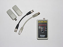
- Continuity tester
-
A continuity tester is an item of electrical test equipment used to determine if an electrical path can be established between two points;[1] that is if an electrical circuit can be made. The circuit under test is completely de-energized prior to connecting the apparatus.[1]
The tester consists of an indicator in series with a source of electrical power - normally a battery, terminating in two test leads.[1][2] If a complete circuit is established between the test-leads, the indicator is activated.[2]
The indicator may be an electric light or such a device might also be fitted with a buzzer.[1] This led to the term "buzzing out a circuit" (which means to test for continuity). This term remains in use today, although any sound produced is usually made by the beeper function on a modern digital voltmeter, but the most simple method that has been used for many years, is a simple curcuit consisting of a 9V battery and a buzzer, with a break in the curcuit to touch what is to be tested at each end to create a complete curcuit and to set off the buzzer if no fault is present.
A popular design has the tester combined with a standard flashlight. A TRS connector or jack plug in the rear of the unit permits a set of test leads to be plugged in effecting a quick conversion between the two applications.
For situations where continuity testing must be done on high resistance circuits, or where delicate conductors and sensitive components that might be damaged by excessive current are present, a low voltage, low current device must be used.[2][3] These typically use an op-amp and watch batteries to drive an LED as an indicator. These testers can be exquisitely sensitive; for example they will indicate if the test points are taken by both hands.
There are times when a simple continuity test fails to reveal the problem. For example, vibration-induced problems in automobile wiring can be extremely difficult to detect because a short or open is not maintained long enough for a standard tester to respond.
In these applications a latching continuity tester is used. A more complex device, it detects intermittent opens and shorts as well as steady-state conditions.[3] These devices contain a fast acting electronic switch (generally a Schmitt trigger) forming a gated astable oscillator which detects and locks (latches) the indicator on an intermittent condition with a duration of less than a millisecond.
To buzz out, a curcuit is usually the first thing that anyone in electrics, when testing cables, will do to locate the break or fault in the connection, and in doing so, see if it is actually the cable or the connecting component that has created the fault.
See also
References
- ^ a b c d "Cable Continuity Tester Info Source". http://www.continuitytester.net/cable-continuity-tester-info-source.html. Retrieved April 28, 2011.
- ^ a b c Dean, Tamara (2010). Network+ Guide to Networks. Delmar. pp. 660–661. http://www.coursesmart.com/network-guide-to-networks-5th-edition/dean/dp/9781423902454.
- ^ a b Dean, Tamara (2010). Network+ Guide to Networks. Delmar. pp. 661–662.
Categories:- Electronic test equipment
- Electrical test equipment
Wikimedia Foundation. 2010.

