- GPO telephones
-
The United Kingdom's General Post Office (GPO) had a number of telephones that were provided by them for connection to their exchanges. Until 1982 the GPO had a monopoly on the provision of all telephones within the UK and so the range was limited. Customers (known within the GPO as "subs", being short for 'subscribers') did not buy their telephones, they were rented from the GPO, together with the house wiring and the wiring connecting the house to the local network at a connection point known as a DP (Distribution Point). The majority of DPs were (and still are) at the top of what are still known in the UK as telegraph poles.
Type 121
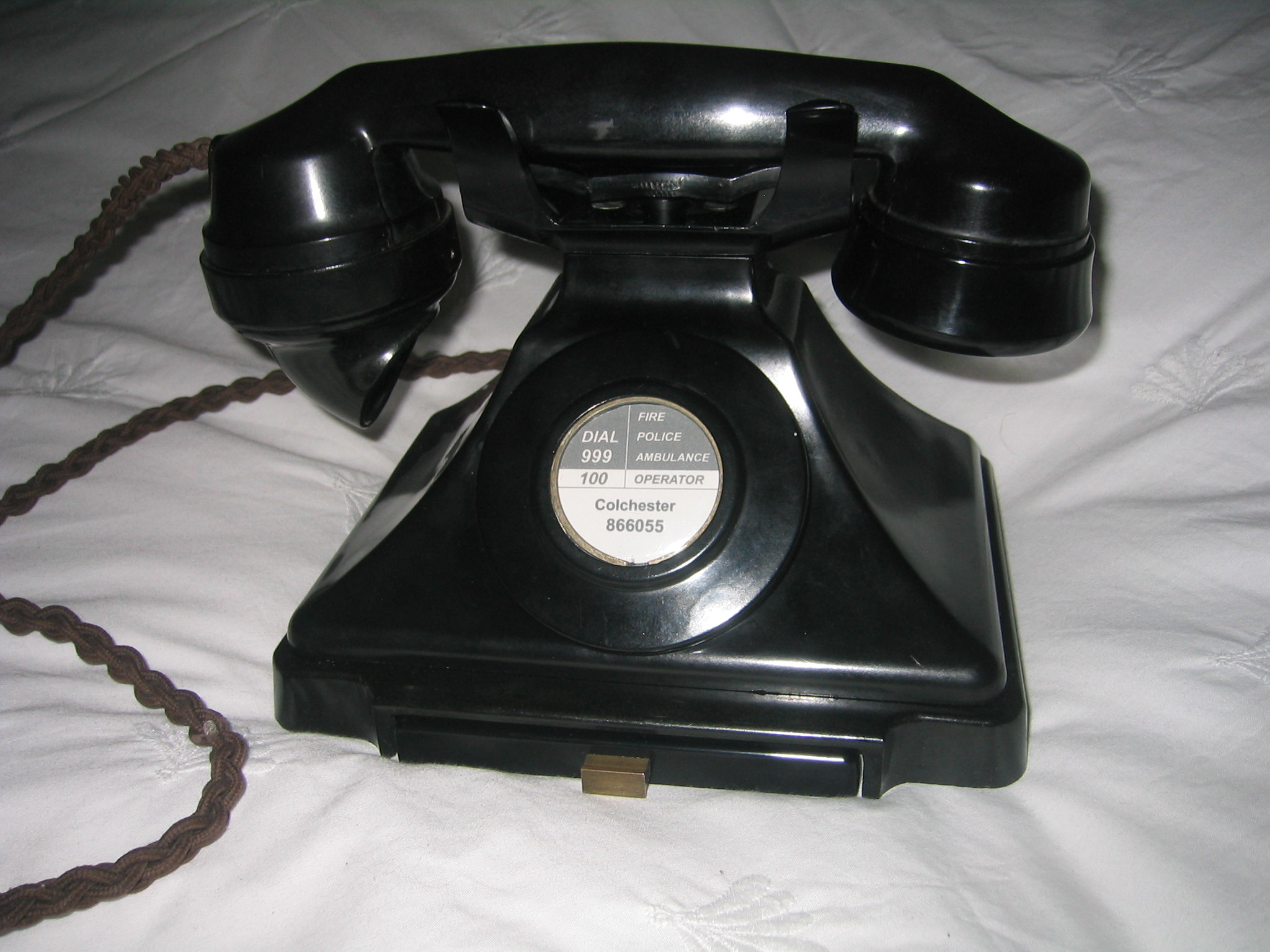
During the early days of telephones, in the UK, a motley collection of instruments were produced, in low volume and crude stylings. Known simply as 'type 1, 2, 3 etc.' these were often used on simple, internal links, sometimes taking the place of the 'speaking tube' in large houses. There were no dials and signalling was taken care of by a hand cranked 'magneto generator'. Often the bell at the other end would just be 'tinkled' by simply rattling the switch hooks up and down. From these developed the first, serious, GPO instruments, the 100 series. This comprised a wall phone, the Tele. 121 and a desk phone, the Tele 150.
Both were based around the same handmade, wooden case, containing the telephone circuit and bell, but unlike the bellset, shown with the Tele 150, below, the Tele 121 had the transmitter mouthpiece screwed onto the front of the box and the switch hook, holding the receiver, protruding from the left hand side. Below the mouthpiece was a dial-mount, which either contained a dial(L) or a blanking plate (CB). This made it a true, one-piece telephone which was available either 'stand alone', mounted on a handsome, wooden, back-board, with integral writing desk or, as a Tele. 123, combined with the original, Button A & B coin-box.
Type 150
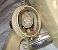
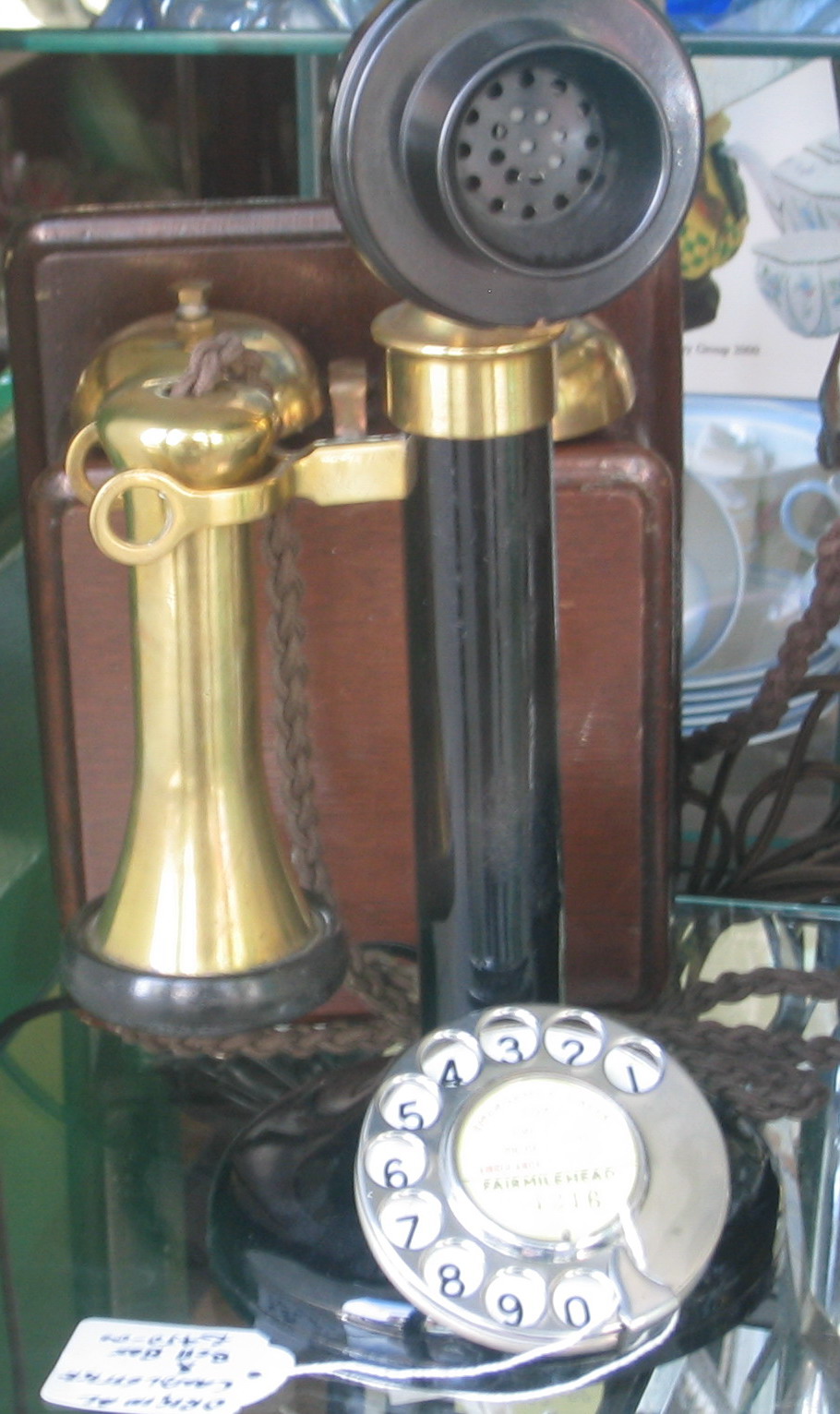
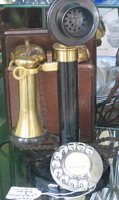 Candlestick
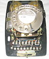
The 100 series, 'candlestick' two-piece telephone is much sought after these days. This one is a Tele. 150L circa 1929. The L denotes the addition of the original slipping cam Rotary dial, as distinct from the CB (central battery) version, which was without any dial and relied entirely upon connection via the operator. As shown this Tele. 150 has been brightened up by the removal of some of the plastic coating which originally covered all of the brass construction. At this time brass was considered a very cheap and utilitarian material, so was usually covered up. The transmitter (microphone) was of a very poor, carbon granule construction, which absorbed moisture and required regular replacement. The low cost, however, ensured that this transmitter would continue to be used for many years to come. In contrast, the twin coil and diaphragm receiver was of very good quality, indeed. The Tele. 150, like its successor the Tele. 162/232, was actually only the 'front end' of the telephone. Containing only the transmitter, receiver and switch hook assembly; the entire electrical telephone circuitry was contained within an accompanying magneto bell set. This was initially the wooden cased version shown or the later, compact, plastic, Bell set 26. The GPO never used Bakelite in the construction of any of its telephones or associated equipments, like the Bell set 26. It was far too brittle. The black material usually confused with Bakelite was always the far more robust material, Urea Formaldehyde.
232 Type
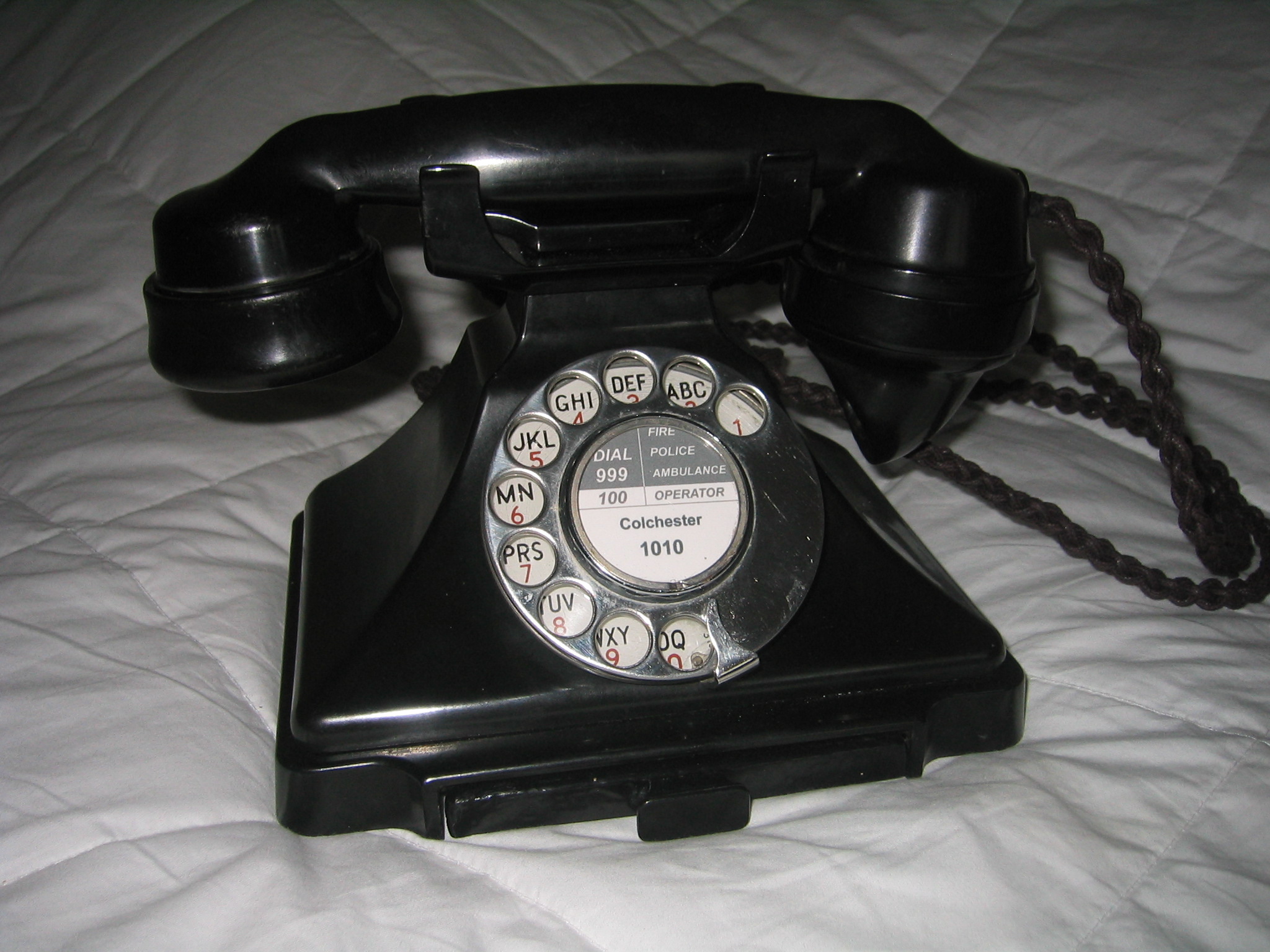
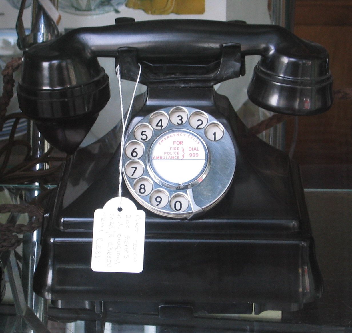
The 200 series was introduced in 1934 and was available for some time alongside the earlier 100 series, which many people preferred. It remained in production until 1957, when it was replaced by the 300 series. The Tele. 232 Handset Micro Telephone, was the first UK phone to incorporate the transmitter and receiver into a single unit, 'The Handset'. Originally launched as the last of the 100 series, the tele. 162, once its potential was realised it was quickly promoted to a series of its own. It was designed as a very lightweight domestic phone, which could be carried around whilst in use, by hooking the fingers under the switch-hook cradle. For this purpose it could be ordered with an extra long instrument cord at additional cost. It was even lighter in CB form, with a blanking plate instead of the dial. Like the Tele. 150, it was an empty shell, which came without any electrics or bells, which was the norm at the time, as a separate bell set was provided. This was either mounted below the telephone or mounted separately in another location. The Tele. 232 came out of the box fitted with a base plate containing a drawer, holding a personal directory card. This base plate was often removed and discarded. The telephone could then be screwed directly onto the matching Bell set 26, making a true, but very heavy, telephone set, or screwed down onto the desk of a CCB (coin collecting box), in a Public Telephone Kiosk. In this form, with a dial which could not be unscrewed from the front and a more durable handset cord, it was re-numbered as the Tele. 242. There was one other variant. With modified internals and designed purely to be used in combination with a Bellset 39a or 44, this was the Tele. 248 in the guise of the Extension Plans 5 & 7.
-
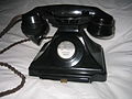
GPO Telephone 232CB, used on manual exchanges
-
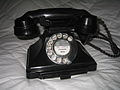
GPO Telephone 232L shown with a dial but without any bells
-

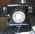
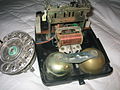
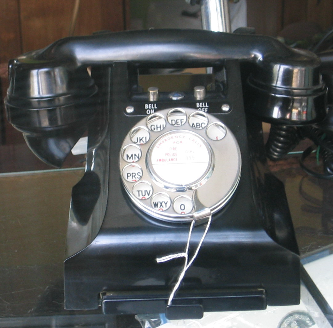
GPO Telephone 232L attached on top of a bell set 26
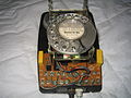
Plan 5 and Plan 7
This was the GPO's first attempt at a compact, supervised extension plan, for small businesses. The Plan 5 had 2 extensions plus the control station, the Plan 7 had only 1.
The main operator control units, of these plans, appeared similar to a 232 plus Bellset 26 combo but was now a Tele 248 plus Bellset 39a (early versions) or 44 (later). These bellsets had a recess, in the front, dominated by a horizontal, quadrant mounted, 4 position slider, flanked by either 1 or 2 press buttons, for buzzing the extension(s). Strangely, these Bellsets 39a and 44 were bellsets in name only. They contained no bell! What they did contain was a maze of spring contact sets, mainly activated by a cam at the pivot of the slide switch. The system required a separate, remote mounted bellset, for incoming signalling. The main unit could make and answer exchange calls, talk to and transfer calls to the extension(s). The extensions could call and talk to each other and the main unit, but could only make external calls if a request to the operator, for the exchange line, was honoured. When this system was eventually revisited and brought up to date, with the 700 series Plans 105 and 107, the equivalent control unit was dubbed 'The Planset'.
332 Type
The 300 series equipments were introduced in 1937. The Tele. 332 ASTIC, Handset Micro Telephone, again available as either L (with dial) or CB (without), was the standard telephone instrument issued by the GPO from 1937 until 1959, although 242Ls continued to be supplied for pay-on-answer kiosks. Essentially it was a redesign of the 232/bellset 26 combo. The ASTIC indicates the use of the advanced Anti Sidetone Induction Coil, to filter a controlled amount of speech back to the talker's ear. It continued in production until the mid-1960s. This was usually only available in black although ivory, red and the especially rare green were produced. Although 332 is the generic for this model, by dint of superior numbers, there were four other models in the range. The glossy, sharp styled 332 gestated from the much poorer quality 330. Though similar, the quality and finish of the moulding was poor. Then there were the button phones. A 332 with the facility for one button is a 312, two buttons a 328 and three buttons a 314. For this reason, in the photos below the instrument on the left is, strictly speaking, a 314 and the one on the right a 312, despite the fact that their full potential is not being utilised. The Tele. 332L shown on the left is a bedside extension from an Extension Plan 1A. Note the addition of the BELL ON - BELL OFF push buttons, forward of the switchook cradle. The centre button position is filled with a blanking stud and only a 2 way label is installed. The instrument on the right has a single blanking stud and the label screws are sitting redundant in their holes.
-
332 Telephone, Plan 1A extension
-
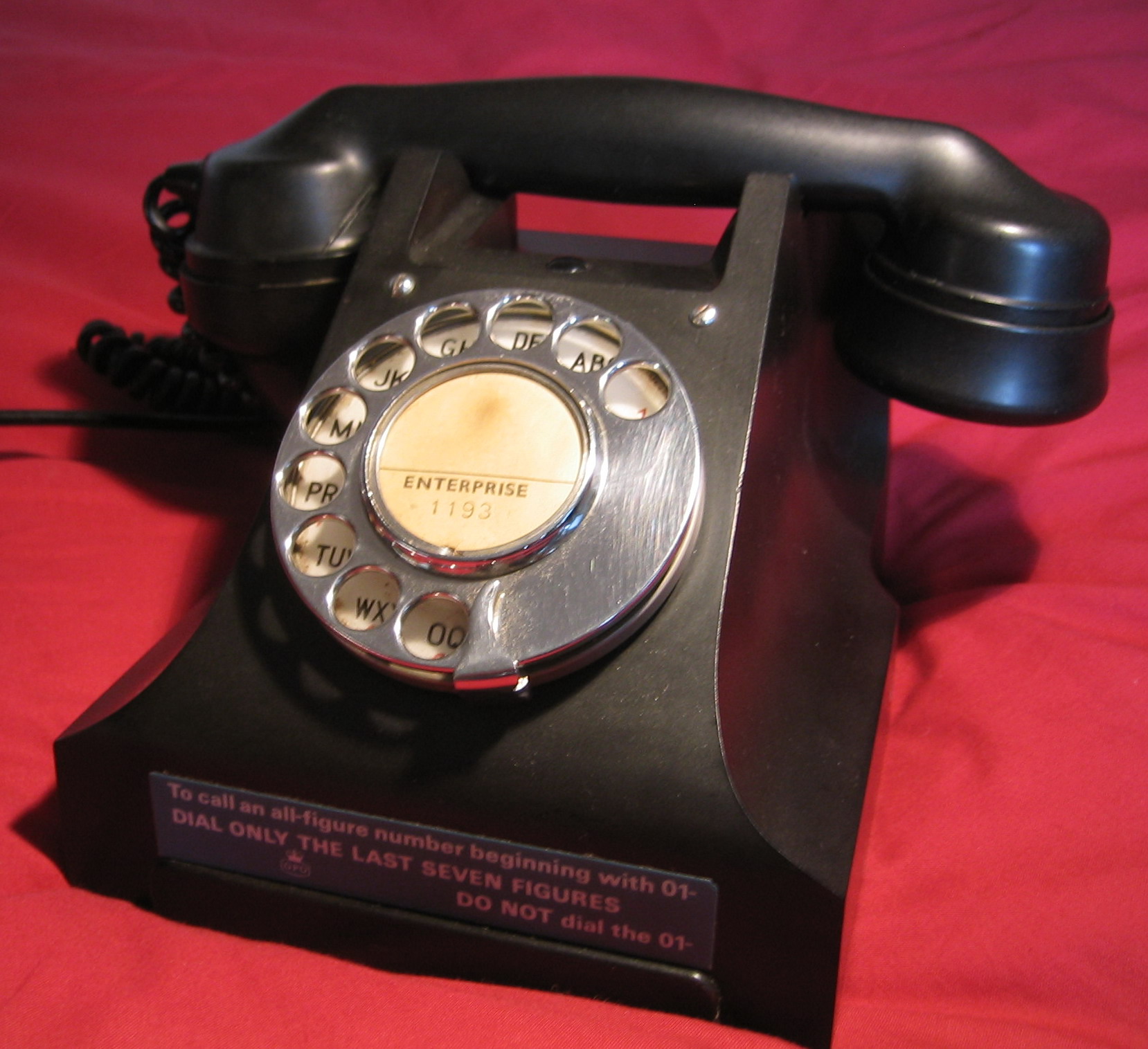
332 Telephone from the Director ENTerprise exchange which was in Southgate, London. This telephone was manufactured in 1946 and factory refurbished in 1963 at the GPO Factory, Cwmcarn, Wales shown by F.W.R. on the base. Interestingly a label attached indicates that the exchange had just converted to all figure dialling as opposed the letters and numbers as indicated by the dial label.
House Exchange System
The 300 series was much more than just the Tele. 332. There was a whole range of similarly designed products. Fieldsets (Tappers), Headsets, Pendant Telephones, Wall Phones and the House Exchange System. Many Private Telephone Companies had sprung up in the UK. As these were banned by law from connecting to external lines, they contented themselves with producing systems for automatically dialling between company offices, within the same building or, via private wires, rented from the GPO, virtually anywhere. The GPO could only do this via PMBXs (manual switchboards), ranging from the 2 to 5 line cordless boards, via the 25 and 50 line plug and cord boards to the mighty PMBX 1A, which, with its modular construction, could be any size a large company might require. The GPO regarded the Private Telephone Companies as a thorn in their flesh and a great loss of potential income. They decided to tap into this lucrative market. Initially they produced a system virtually identical to the competition and called it the House Telephone System. This appeared, from the rear, like a Tele. 332 but the front sloped down and was covered in two rows of buttons, by which a few other, similar, extensions could be called. Like the competition this system was entirely internal and could not connect to the PSTN (Public Service Telephone Network). Unlike the competition, however, the number of extensions which could be incorporated was strictly limited. The GPO tried again.
The 300 series House Exchange System, now known as the HES1, was a combination of the Tele. 332L and the House Telephone System. From both the front and rear elevations the instrument appeared as a normal 332L. From the side, however, it was a different story. The snout of the instrument had been stretched forwards a full 8 inches in order to mount 2 rows of call buttons, along with their plastic covered labels, forward of the switchooks. All stations could make and take external calls, call any other station and also transfer calls between them. For the first time, small companies did not need to employ a telephonist. A big selling point.
Bell Sets 25/26/31/56/59
These were bell sets that could be used, either stand alone or attached to the base of a 232 type telephone or similar, to provide a complete telephone instrument, as Tele. 150s and Tele. 232s did not themselves have an integral telephone circuit or bell. For this reason, although mostly black, they were available in the full range of colours to complement a coloured instrument. All these bellsets appeared identical externally, with a contoured, moulded cover which looked stylish alone, but would dock firmly underneath a 232. They were all based upon the same baseplate but differed in the type of bell and whether this was alone or accompanied by a capacitor, and / or an induction coil and any other telephone circuit components and wiring.
Bell Sets 64/67
Electrically identical to Bellsets 26/56 but with an all-weather case and externally mounted bell gongs, for use where much more volume was required.
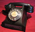
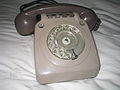
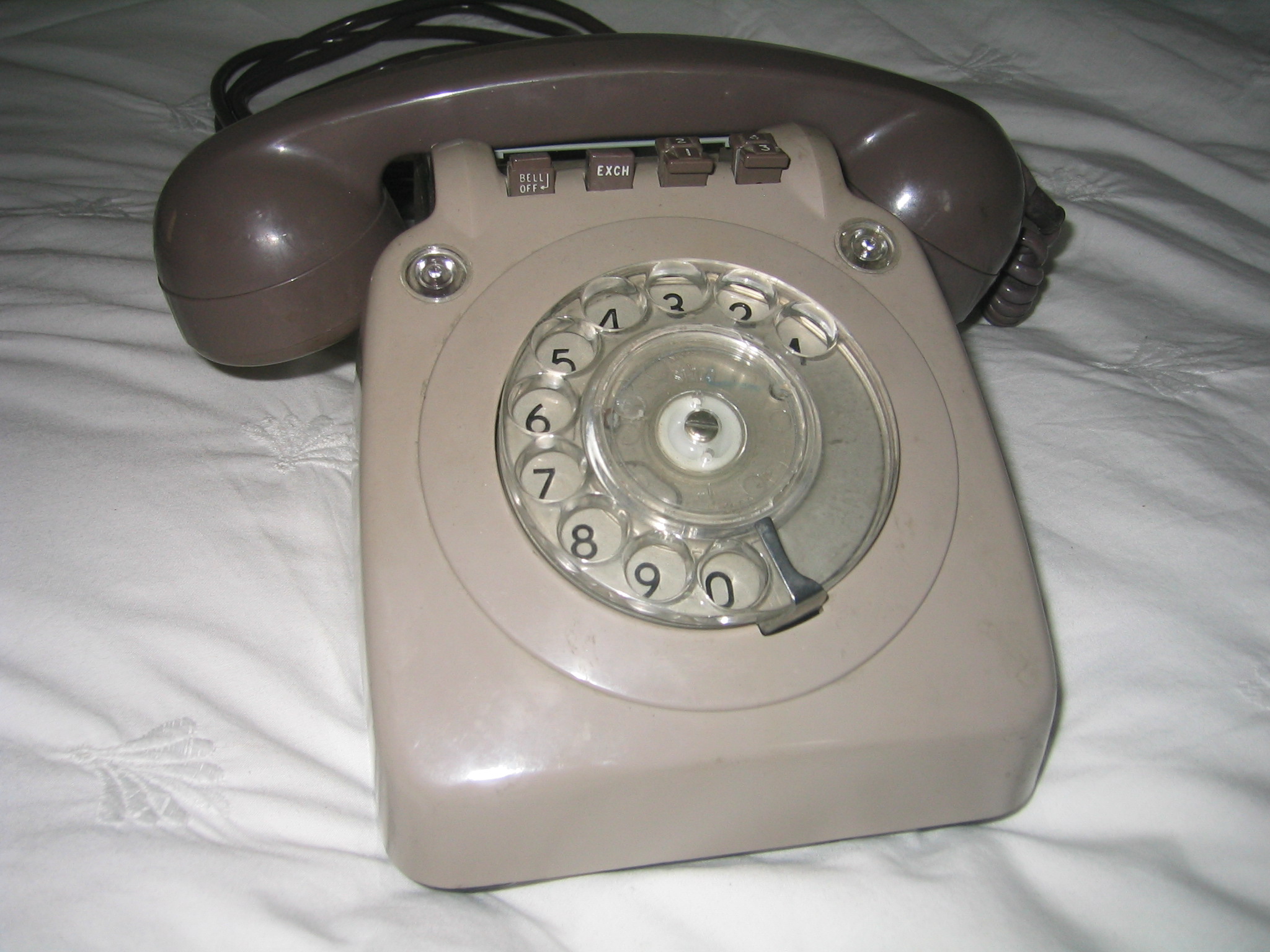
706 Type
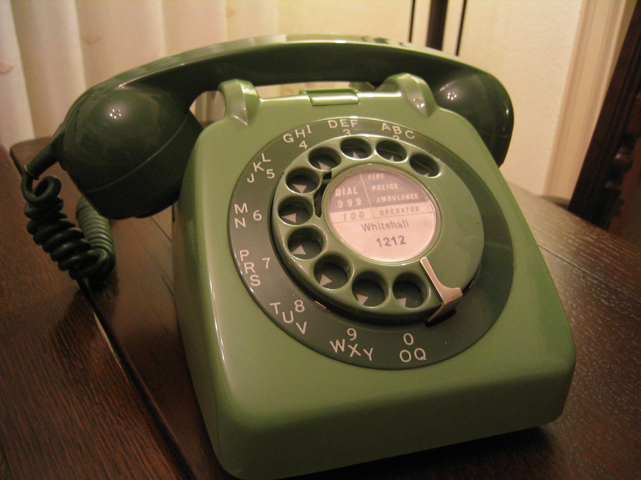
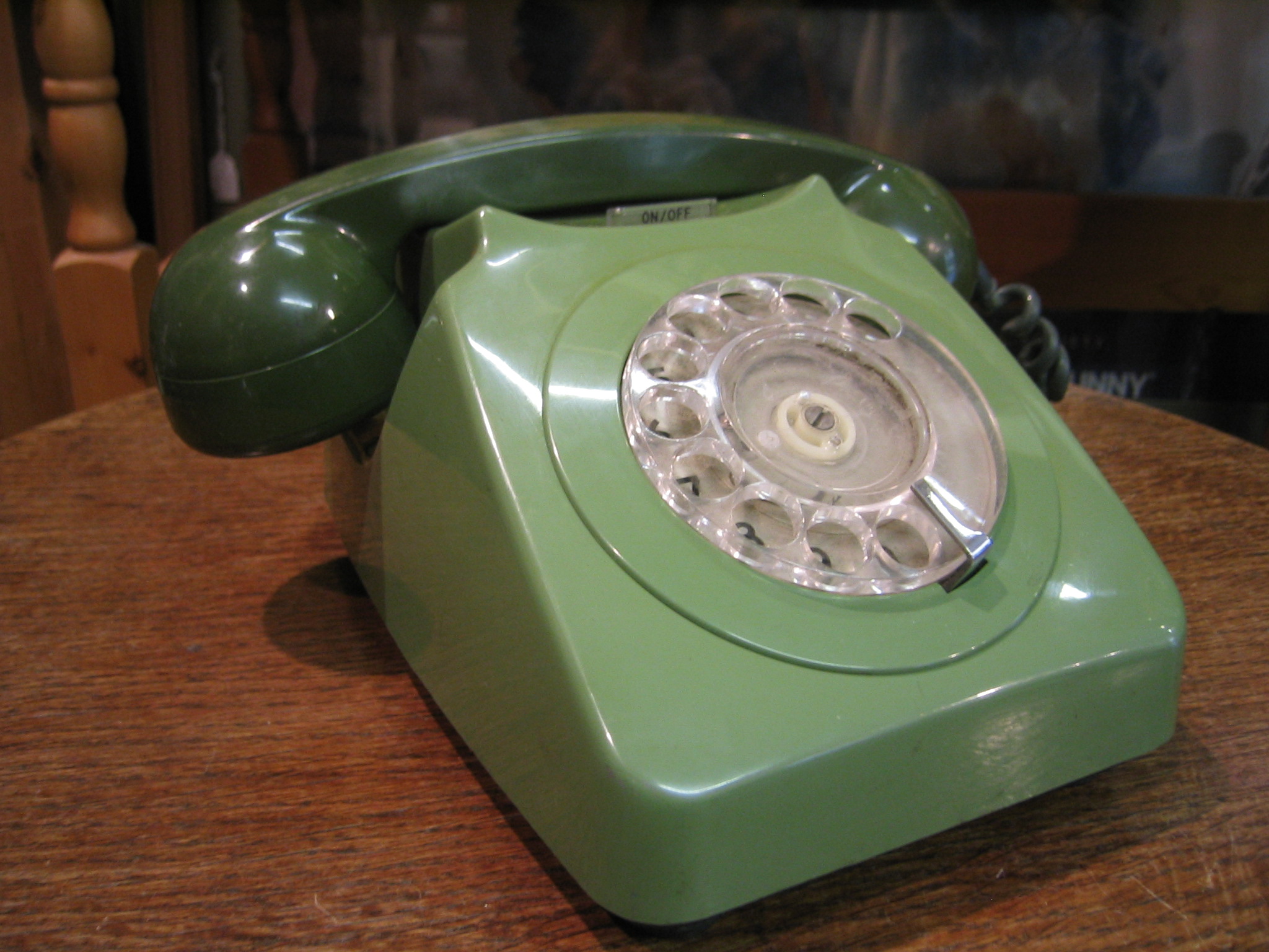
The 700 series was the GPO's response to publc demand, fuelled by American television shows, for a modern design with a helical, anti-tangle handset cord. The Tele. 706L Handset Micro Telephone was a revelation when it was first released in 1959. Again, still available in CB (no dial) form, it was a robust design which is still in use today in the UK, suitably modified for use with the New Plan BT sockets. It was available in two-tone green, two-tone grey, topaz yellow, concorde blue, lacquer red, black and ivory. Manufactured to a GPO design, examples manufactured by various companies displayed several differences. Some had a metal baseplate, others plastic. Some had a printed circuit, others a wiring loom. Some had an outer dial bezel with the numbers/letters on it, some had a plain bezel and a normal dial. More importantly, to the users, some came with a plastic or metal handle between the switchook cradles, so that it could be carried around in use. Just like those on American TV.
-

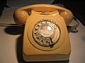
706 Two Tone Green Telephone manufactured 1963. This sample unfortunately has a cracked dial, but is an early version as later dials were clear
-
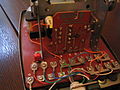
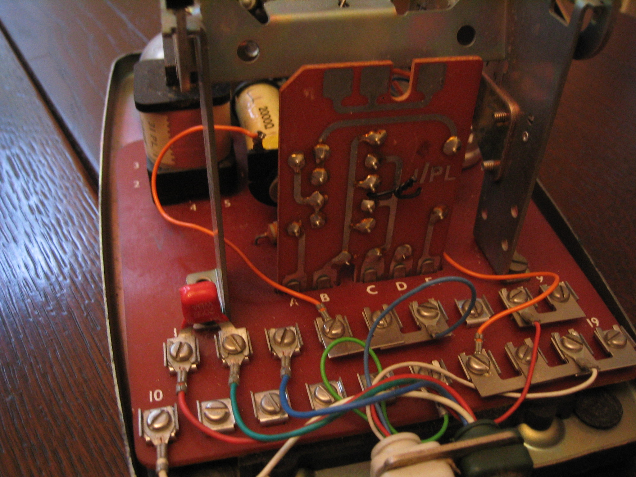
706 Telephone inside showing the reversible regulator mounted vertically and shown in circuit
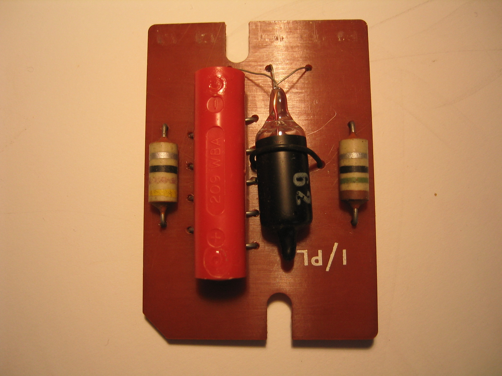
A feature of the 706 was a regulator that could be used or not. The idea was if the subscriber was close to the exchange, the regulator would reduce the sensitivity as it had been found that this telephone was too sensitive close to the exchange and also had a propensity for picking up radio broadcasts from strong stations, mainly taxis. The purpose of the regulator was to vary the amount of ac speech current flowing through the transmitter and receiver, to prevent it being considered too loud by subscribers on short lines. The regulator consisted of a network of rectifiers, diodes, resistors and two thermistors.
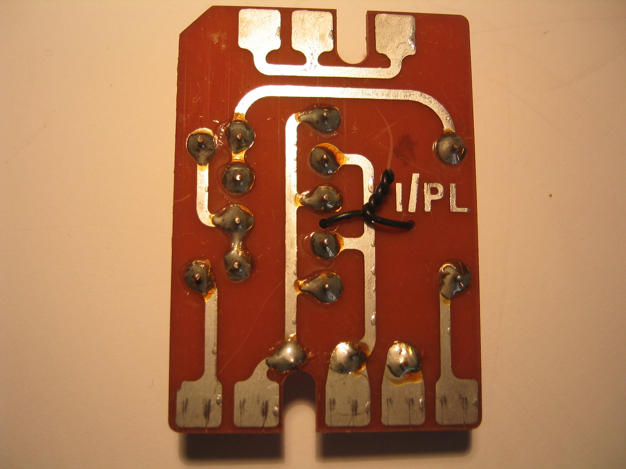
The regulator could be removed for customers not close to the exchange by inserting the shorting part of the regulator and this was achieved by turning it upside down.
The regulator being used was the default and in practice the unit was normally left in circuit. Compare this with the inside of a 746 where the regulator is permanently built in.
-
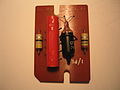
706 Regulator unit, the red part being a string of diodes and the glass part are the thermistors. Note the thermistor is painted black so stop the glow being shown
-
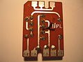
706 Regulator reverse]
NB: There were a number of hybrid types between the 300 and 700 series. These appeared as 332s but fitted with a 700 series handset and cord. The most interesting of these were the 'Intinsically Safe Telephones'. These had 323 style bodies of a sealed metal construction in a grey hammer finish. These were for installation in environments where there was a risk of fire or explosion from sparks, such as mines and chemical plants.
The 700 series was much more than just a single instrument. There were the Teles. 710, 746, the 711/741 wall phones, pendant telephones, headsets, re-styled bellsets, connection blocks and distribution panels. A full, matching range. Then there was the HES3.
House Exchange System No.3
All 700 series telephone instruments came with at least one knockout forward of the switchooks, for installing bell on/bell off switches for instance. Some, however, the Tele. 710, came with four smaller knockouts and, if you looked inside the case, two circular ones too, top right and left of the dial aperture. These, along with a host of unused holes and bracketry, on the chassis, were a source of mystery for a time. Until, that is, the small business successor to the 300 series, House Exchange System 1 was revealed. The 700 series, HES 3.
This comprised, up to, five stations, all of which could call one another and make, answer or transfer calls. All of the parts of this system had to be built up, on site, by a High Grade Fitter, from an assortment of anonymous looking cardboard boxes and plastic bags. After installing the fixed wiring and external power supply, up to, five ordinary looking 710Ls had to be transformed into Extension Stations by removing all the knockouts and stuffing them with an incredible amount of springs, wiring and lights. Incredibly, two of the knockouts could wind up, for a full system, containing two pushbuttons each, one for each of the other four stations, L shaped to cram them into the small holes. That made a total of two supervisory lamps and six buttons on what, outwardly, seemed a normal, domestic telephone instrument. Getting the case back on took some doing.
-
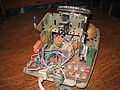
Probably the ultimate development of the 700 series telephones. A HES 3(House Exchange System) built into the shell of a 710 telephone.
-
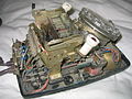
Showing the inside of an HES 3 instrument, crammed with parts
710 Type
This was the same as a 706 but had four possible buttons or lamps fitted at the top of the case. Dummy buttons were used where neither button nor lamp was used. The ultimate task of the Tele. 710L was that of being transformed into an Extension Station of a House Exchange System No.3.
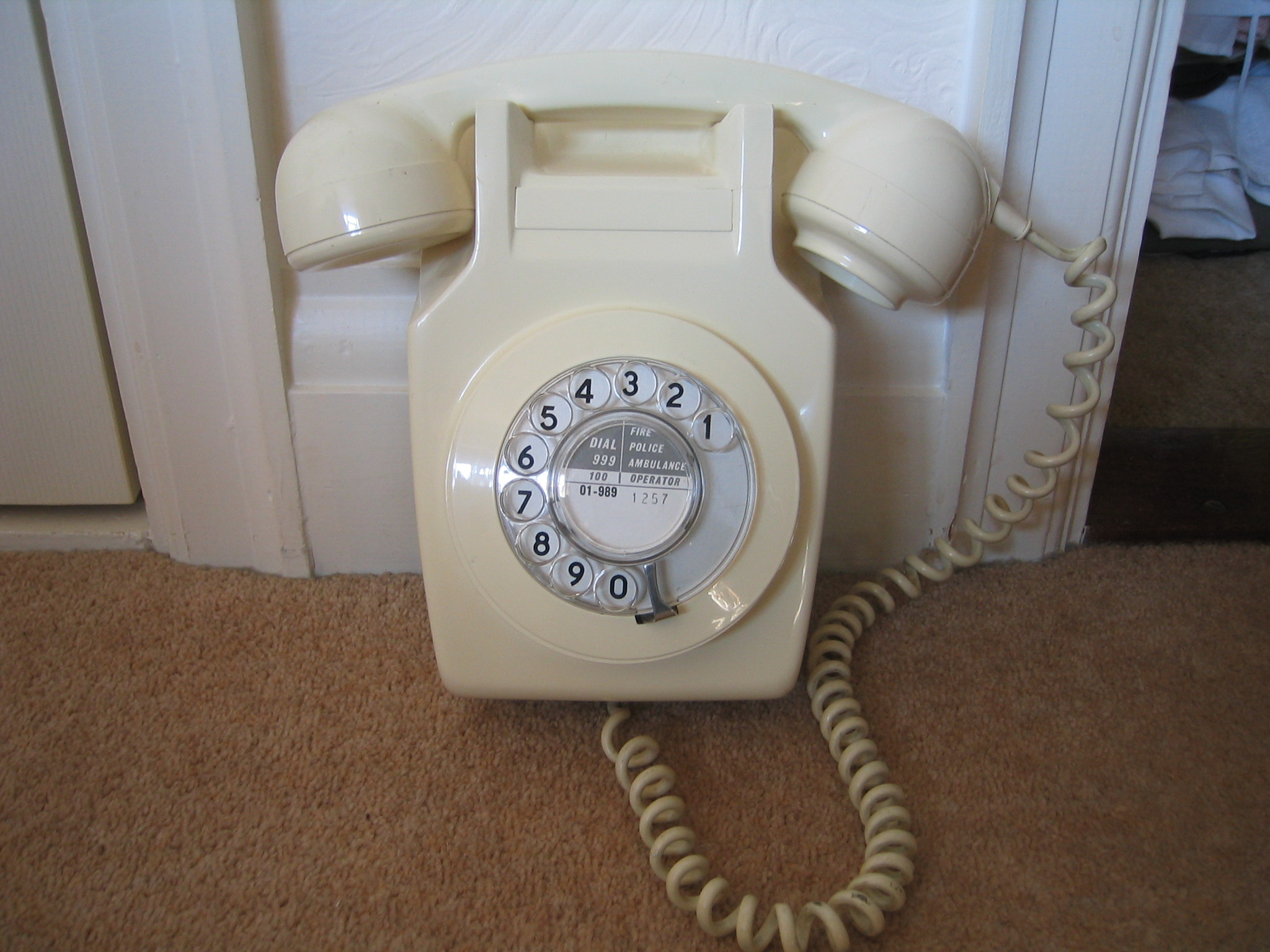
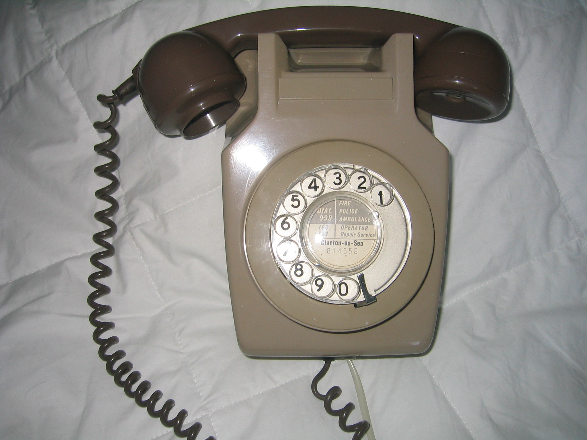
711 Wall Mounted
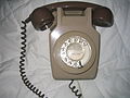
Initially with the 700 series, when a subscriber (customer) ordered a wall-mounted telephone, the attending fitter would have to requisition a standard Tele. 706L, a Bracket No. 6 and a modified, stainless steel, switch-hook assembly. On site the 706 would have its case removed, the front two feet knocked out, the instrument cord removed and the dial turned round through 180 degrees. The bracket was then screwed to the wall, the baseplate mounted on the bracket and the fixed wiring, having been led in via a hole in the baseplate, was terminated in place of the instrument cord. The two metal bezels by which the case was fastened to the chassis were removed and replaced by the new switchhook assembly. This had a bridging piece, like the carrying handle, but with two large hooks to stop the handset falling to the floor. If the instrument had an early dial bezel, carrying the letters and numbers, then this too had to be rotated 180 degrees. When reassembled, the result was an untidy compromise. It looked like what it was, an upside-down 706 with its handset hanging ungainly from the bottom and the curly cord dangling beneath. It was a relief to all concerned when all the above became unnecessary with the introduction of a purpose-built instrument.
Tele 711L
This was, essentially, a 706 base with a modified chassis and case. First introduced in 1961, it too could have either a steel or plastic base and wired or printed circuit internals, depending upon the manufacturer. It was supplied with the T-shaped Bracket no.6. The hooks on the top of the bracket located into the holes usually filled by the front feet. A single screw then secured the rear (bottom) of the baseplate to the bracket's upright. Only two rubber feet were left in place, to support the lower part of the instrument on the wall. There was no instrument cord, the fixed wiring being led directly in via the oblong hole on the lower left. The picture below shows one of the last 711s, having been made in 1968, the last production year. The 711 was superseded by the 741 shortly afterwards.
-

711 Wall mounted Ivory Telephone
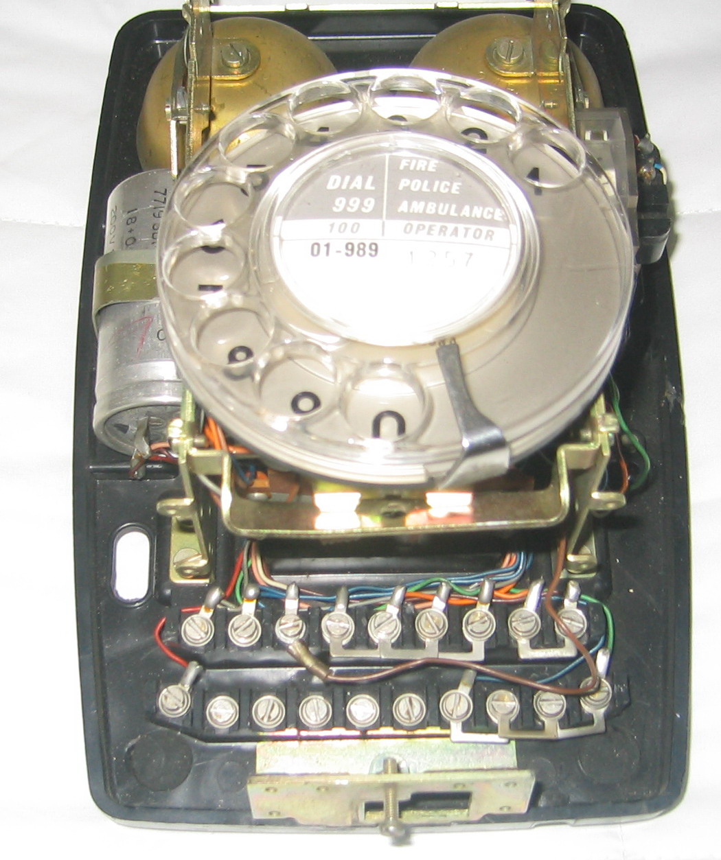
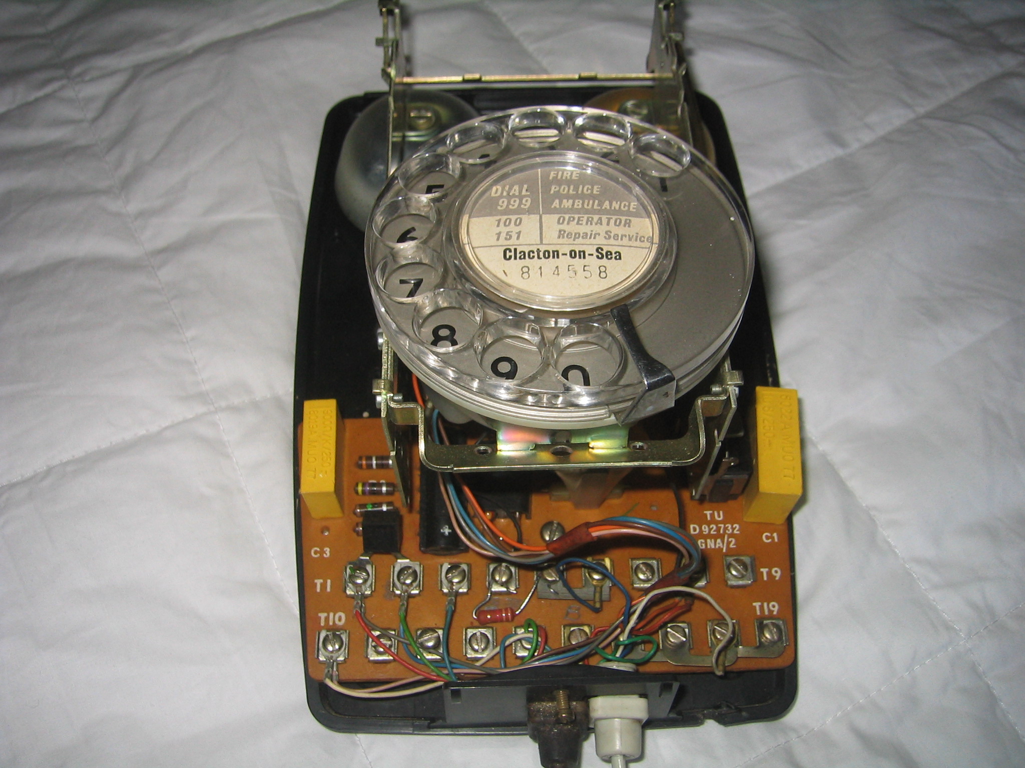
-
The inside of the 711, note: wired with no PCB, shown without handset attached
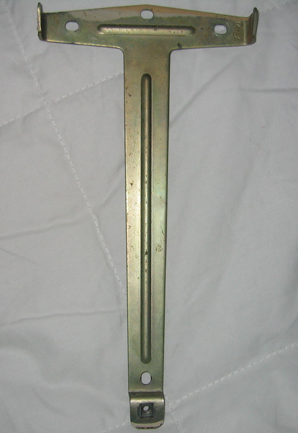
-
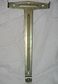
Telephone Bracket No. 6 required for mounting wall telephones and other devices
712 Trimphone
Main article: TrimphoneIn the spring of 1964 the GPO broke with tradition, in a big way, with the launch of the Tele. 712 'Luxury Bedside Extension'. It looked like a wedge of cheese with a big 'L' on top, and its only role in life was intended to be on every trendy bedside table in the land. It lit up in the dark and chirruped, softly, at any volume you chose, to ease you from your slumber. This was obviously going to be BIG, the marketing men said, so they ordered a shed load, a very large shed, and sat back and waited for the avalanche of orders. It never came!
What happened then was one of those things which you just couldn't make up and get away with. Back then, as now in the UK, sadly, public telephone kiosks suffered a high level of vandalism, especially over each weekend. The Tele. 242s, which were still being used with the old 'Button A / Button B pre-payment coin-boxes, were routinely destroyed. Replacing them was expensive, and the promised pay-on answer 700 type vandal-proof coinboxes were shortly due to be introduced. Ordering a minimum quantity of 'new' Tele 242s would be expensive, so what to do? Well, someone reasoned, why throw good money after bad when we've got a warehouse full of Luxury Bedside Extensions going nowhere near anyone's bedside anytime soon? Why not install the Tele 712s in call boxes, on a temporary basis? So they did just that.
Of course, what happened then was totally predictable. As fast as they were installed, they were stolen! Then, as they began to appear in peoples' homes and on executive desks, this began to generate a demand. It was the best marketing accident ever. What they had got very wrong was their target market. No-one was going to pay good money for a space-age accessory and hide it in a bedroom. They wanted it up-front and on display. There obviously had to be a change of name. So it was goodbye 'Luxury Bedside Extension' and hello 'Trimphone', acronym: Tone Ringing Illuminated Model. The 'illuminated' was the transparent plastic dial ring, that was lit by a tritium gas tube, which did not require external power but were later replaced by other methods of illumination.
The Trimphone finally proved so successful that it was updated, in 1966, to the Tele 722, to fit it better for its new role, and eventually even push-button versions had to be developed, in the form of Tele 766 (pulse dialling) and 786 (tone dialling). To make it even more attractive, a huge range of colour combinations was eventually offered to suit any decor.
Stranger yet, the popular BBC TV programme 'That's Life' had a long running feature culminating in a competition for best impersonation of the Trimphone sounder by either a human or bird.
741 Wall Mounted
The Telephone 741 was first introduced in 1968 to replace the Tele.711, it had the same case as the 711 but was based on the internals of the Tele. 746, with its integral regulator and extra button capacity and lamp bracketry.
-
741 Wall mounted Two Tone Grey Telephone
-
The inside of the 741. Note PCB on this metal based example.
746 Type
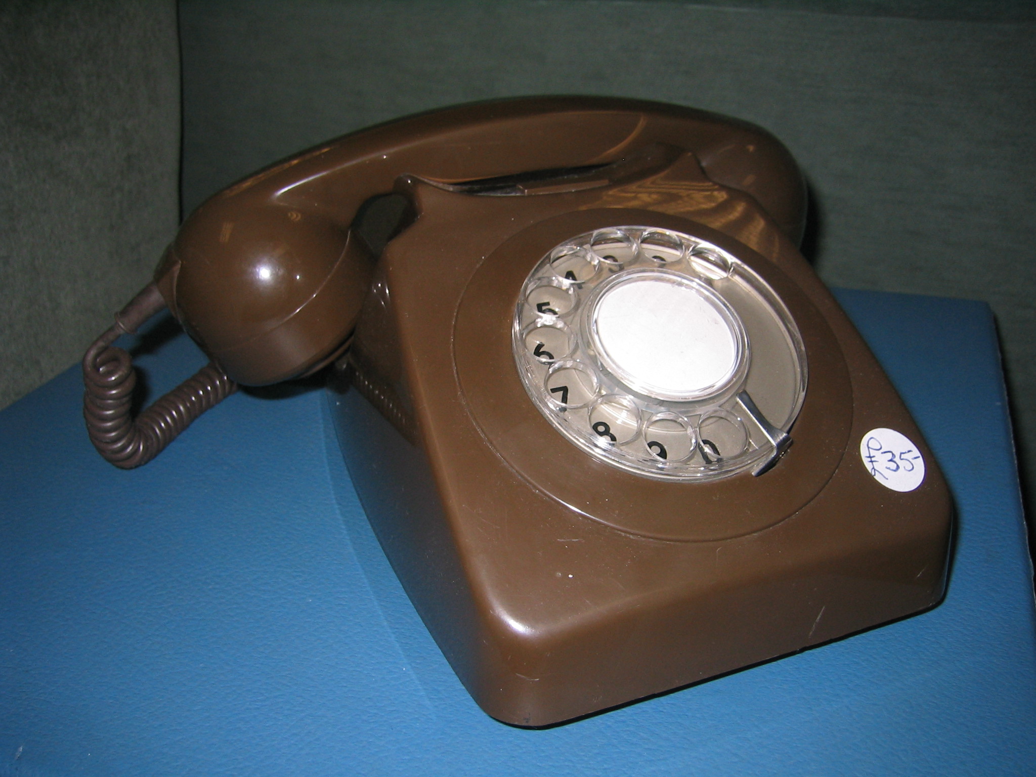
This was an updated version of the 706L type. It was introduced in 1967 and looked very similar, although it had a slightly different case design. The 746 "carrying handle" was part of the moulded 'cow horn' switchhook cradle, whereas the 706 had a replaceable (or indeed removable) plastic or sometimes metal carrying handle. Another way of telling them apart was to look at the stamping on the base. Unlike the 706 type it had a built-in regulator that could not be removed. When modified for the 'New Plan' plug and socket system an 8 was added to the numbers, hence a 746 became an 8746. Strangely, a brown case colour was added to the range.
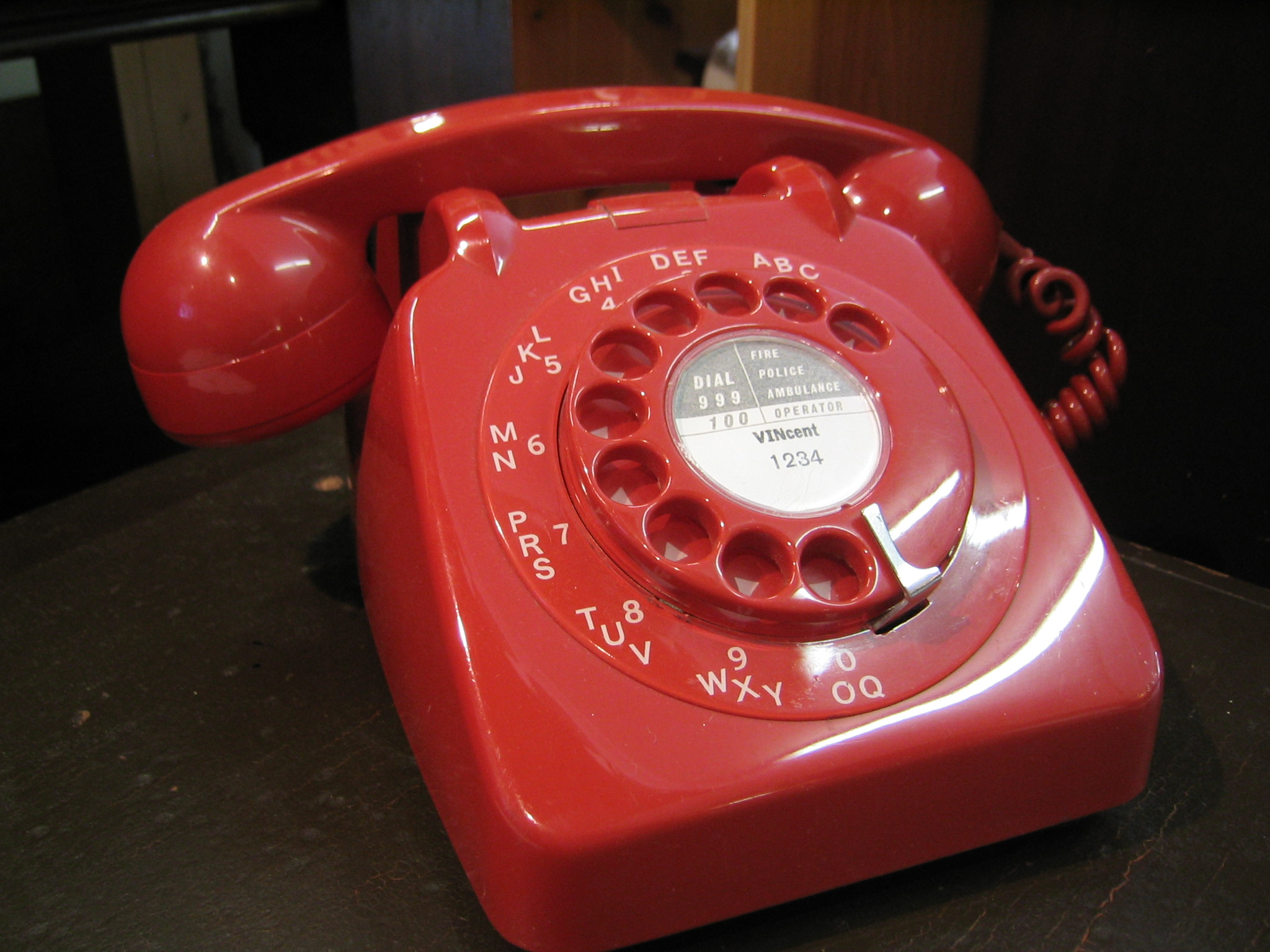
-
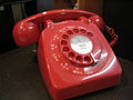
For comparison, a Tele. 706L Red, an early version with coloured dial and lettered outer bezel. Pre. All Number Dialling
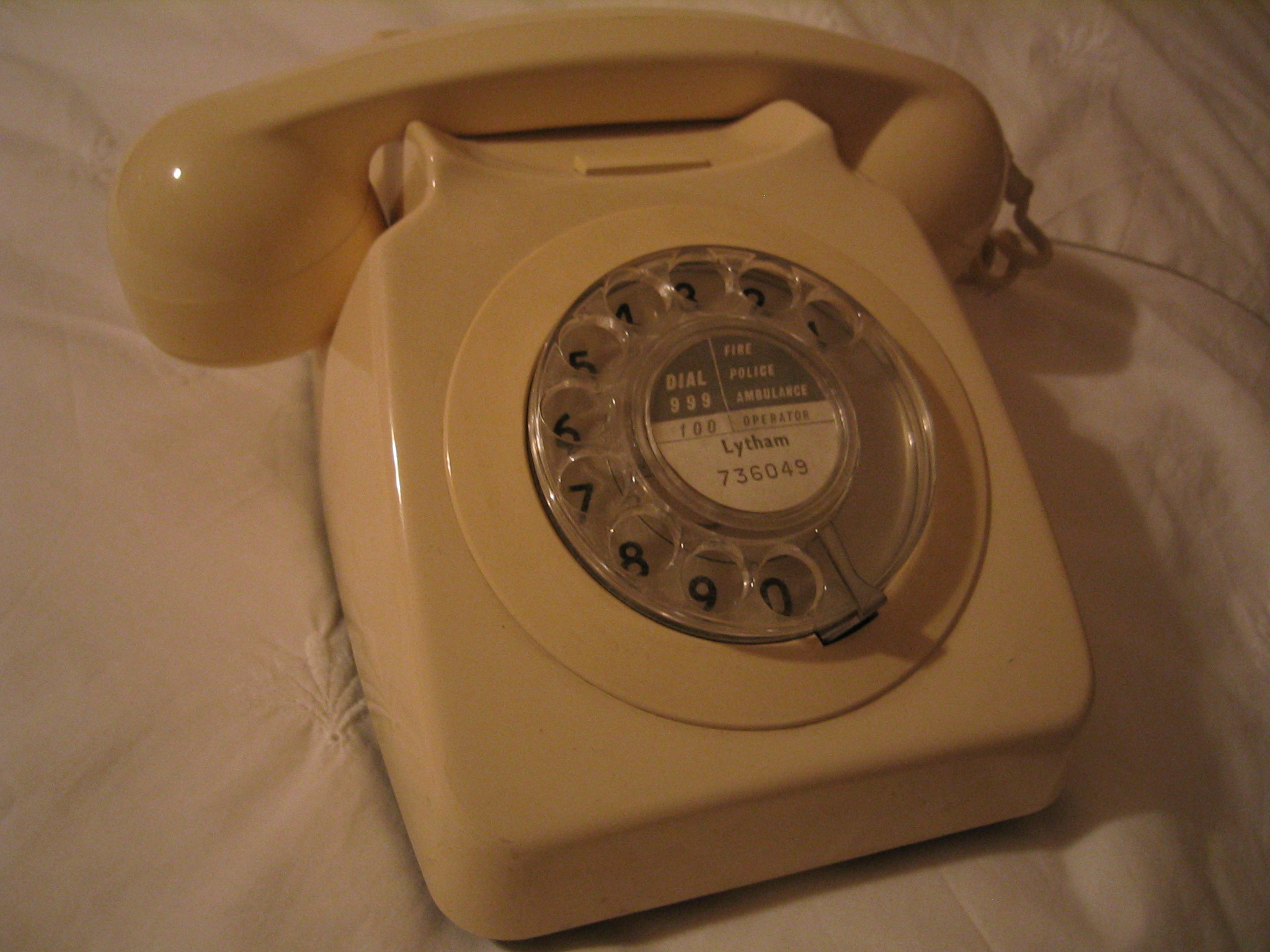
-

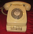
Tele. 746 Ivory, manufactured in 1984 and still in use today, having been converted to use the 'New Plan' plug and socket system.
-
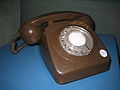
Tele. 746 Brown, an unusual colour which was added to the range at the introduction of the 'New Plan' socket wiring system
-

746 Inside showing built-in regulator, which can be identified by the green centipede-like diode pack, beside which are the thermistors
With modern exchanges the regulator is not required, but, although it can be removed from the 706, as shown above with the 746 the regulator is permanently wired in-circuit and cannot be removed.
-
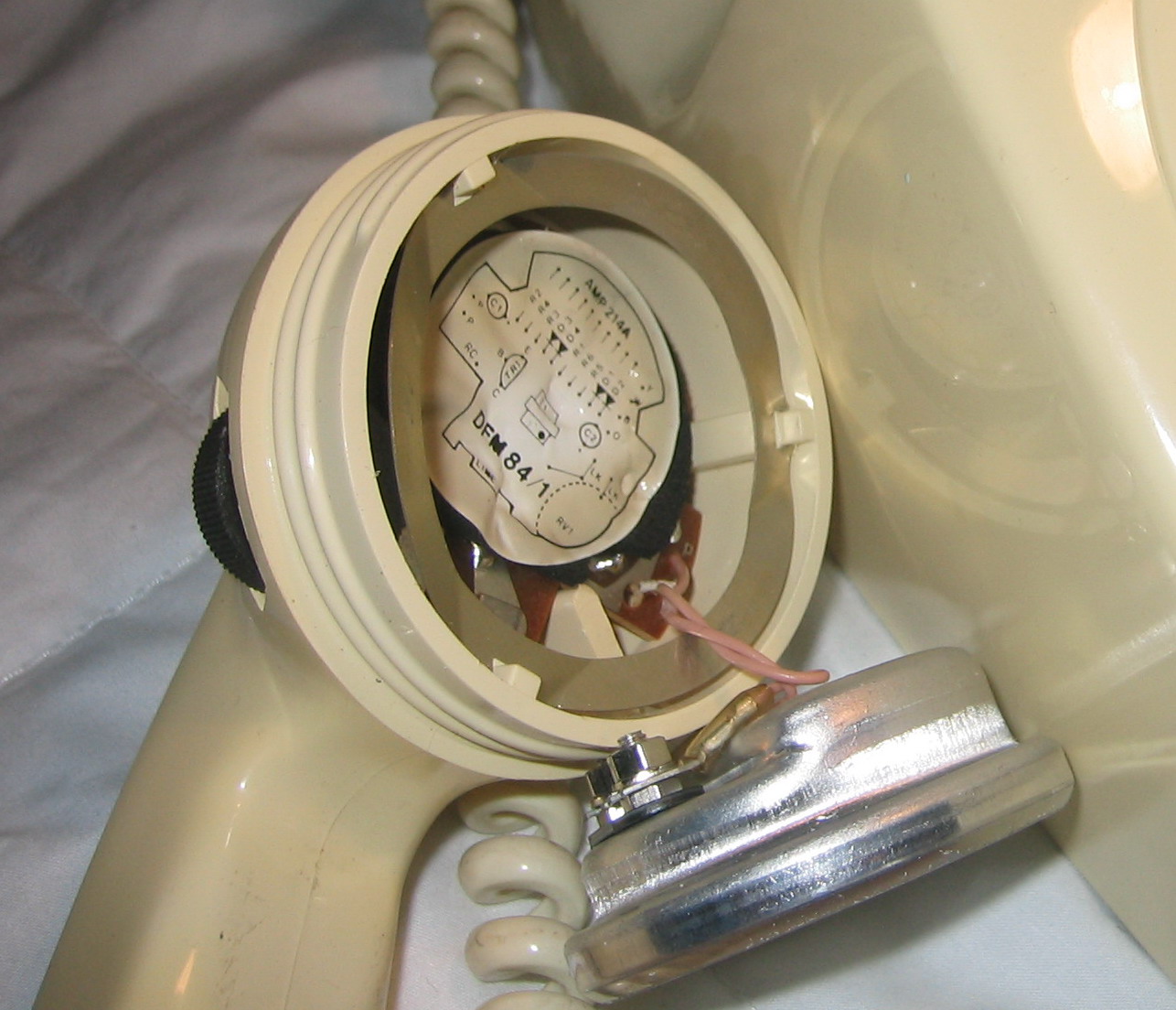
700 type, Amplifying Handset 214A, for the hearing impaired, with thumb-operated volume control on the side. Supplied as an optional extra for any 700-type instrument, this handset was also available with 'Lamp Signalling': a neon lamp, mounted in the top centre of the handle, flashed whenever the bell rang.
-
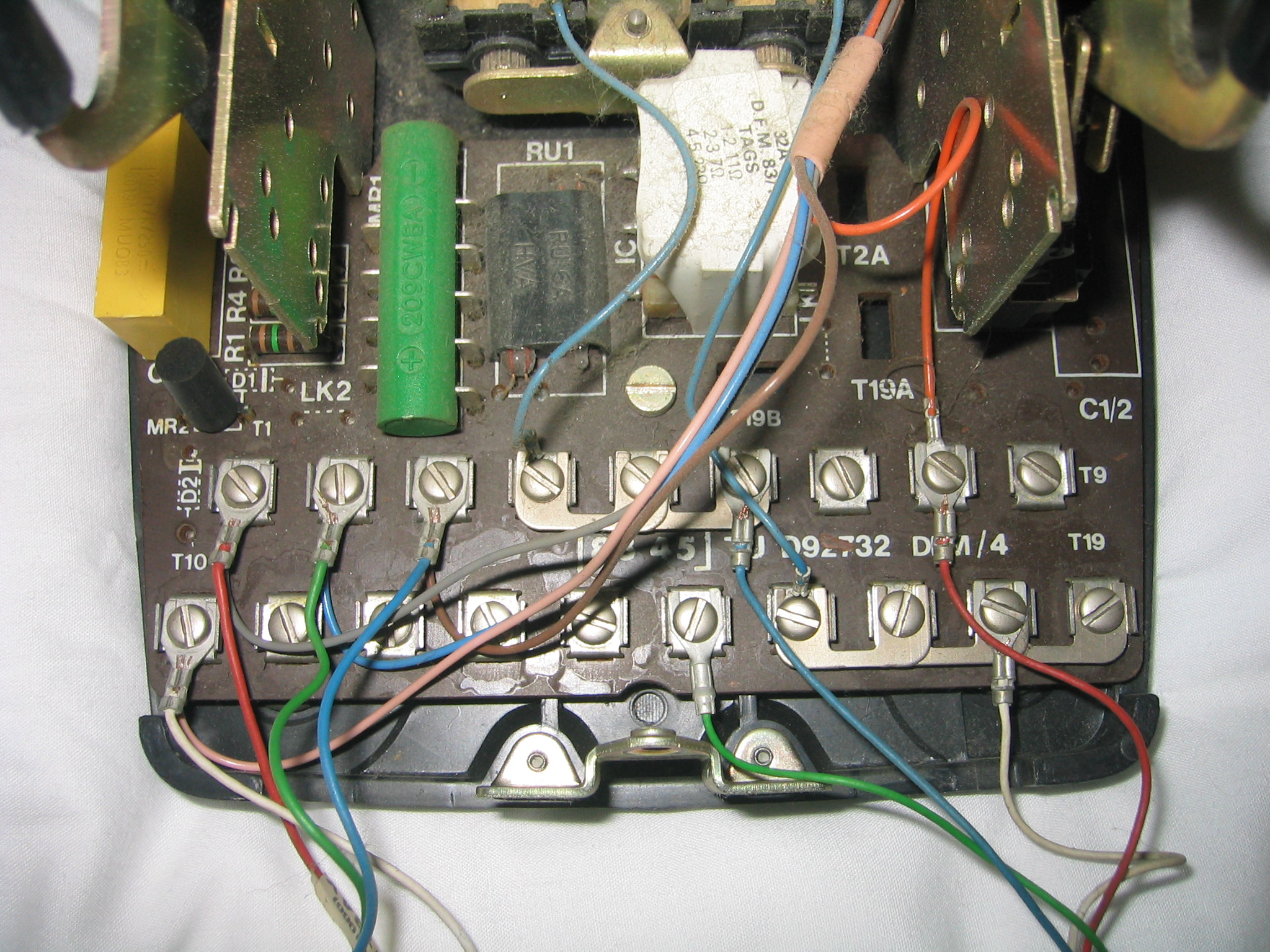
The lower cost Bell Type 79A used in the later 746 telephones. With the dial de-mounted, the chassis clearly shows the bracketry for fitting up to five locking or momentary-operated auxiliary switches. This feature was carried over from the Tele. 710.
The 700 series was able to have between one to six additional buttons fitted; these could be used for many purposes, of which the earliest was for seizing the line and getting Dial Tone for subscribers on Shared Service (party lines). The one shown in the picture was commonly used on bedside extensions, Plan 1A, to turn the bell on and off. If no button was required, the blank was left in place.
-

A very well used Tele. 746, manufactured in 1971, which spent its working life at a scrap merchants. Again an extension, with a bell on/bell off button. The main telephone may not have a switch as one bell must always remain in circuit.
-
Inside the green 746L, showing the single switch, centrally mounted on the five way bracket.
756 Type Push Button
Just as the 700 type came about as a result of public demand. fuelled by US television shows, so the advent of 'Touchtone Dialling' in later American TV output brought about a demand for the same at home in the UK. Unfortunately the GPO did not yet have the exchange equipment necessary to support 'Touchtone' or DTMF (Dual Tone Multi-Frequency) as the GPO preferred to call it. So they decided to introduce a simulated version instead. This would comprise a very ordinary 700 type instrument, with a push button mod. kit fitted. Beneath the smart-looking buttons, a small converter circuit, powered by re-chargeable ni-cad cells, would convert the button presses back to perfectly normal, 10 impulse per second, loop-disconnect dial output, i.e. the new keypad was made to simulate an old rotary dial.
But this was the GPO, and nothing was ever that simple. Even though all the design research had already been done by the major US companies, The GPO decided to do it all over again. Although, initially, they decided to modify the existing 700-type instruments, what hadn't been decided was how the push-buttons should best be laid out. Completely ignoring the then-standard US layout, an experiment was put into motion at the Dollis Hill Research Centre. Mock-ups were made of every conceivable combination and layout of buttons. Each of these had its own seated operator and digital readout. All the button pads and readouts were cabled to a primitive computer. For weeks on end the computer flashed random series of numbers to the digital readouts and the operators had the task of punching these numbers, as quickly as possible, onto the keypads. The speed and accuracy rate were continuously logged, as was the ergonomic comfort of the operators. At the end of many months, much expense, and to absolutely no-one's surprise, the results came out in favour of the existing American layout! Sadly this was too late for at least one major company. ICI had decided to press ahead unilaterally with their own design, which had two rows of five buttons (no # or * buttons then) set horizontally across the centre of a circular face-plate. This proved very awkward to use.
This was the outcome of the trials. A perfectly normal Tele. 746, but fitted with push buttons instead of a dial and re-dubbed 756. The push buttons just created the same loop disconnect signalling pulses as a dial telephone, which caused horrendous post-dialling delay and much knuckle rapping frustration.
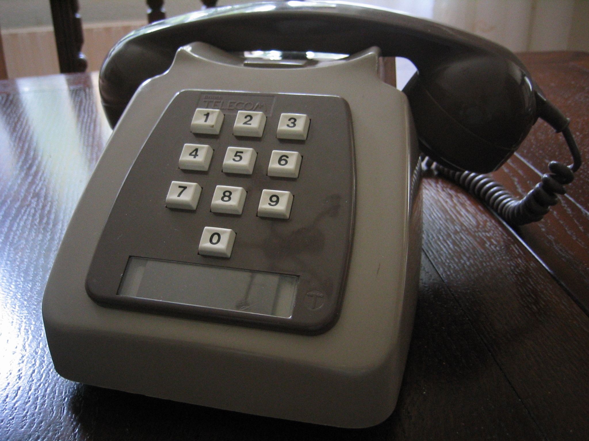
The model shown in the photograph is actually an 8756, which has been modified to enable it to be used with the 'New Plan' plug and socket system.
-
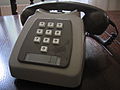
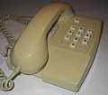
8756 Two Tone Grey Telephone
-
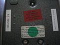
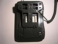
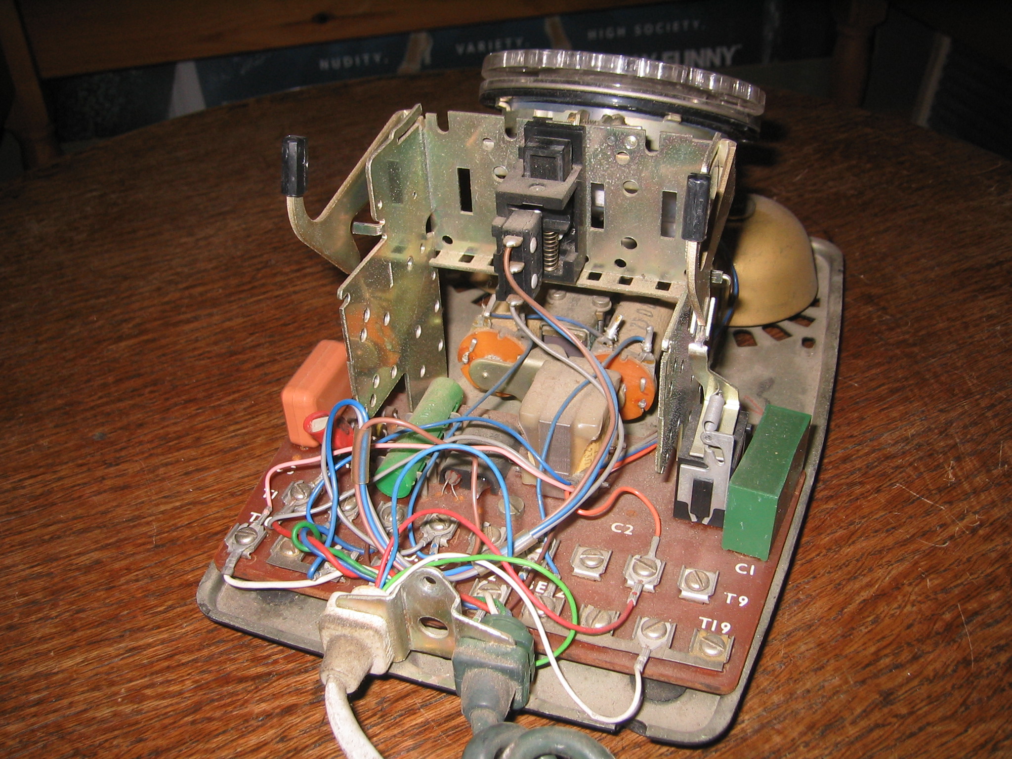
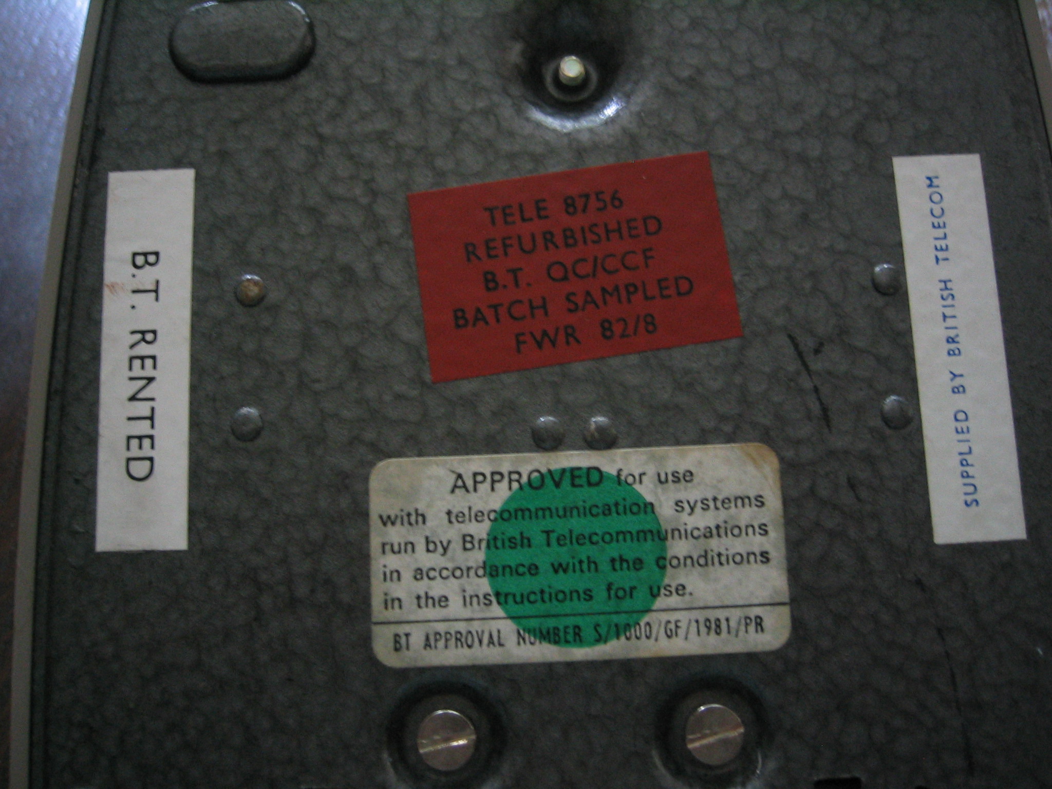
8756 Base, showing that this telephone was refurbished in 1982 and that this was a telephone rented from BT
782 Type Push Button
This was a 746 type telephone which could handle MF4(DTMF) signalling which produced tones. Obviously these telephones could only operate to exchanges that could deal with MF4 but they were used on PABX systems that used MF4 for internal calls from the 1970s. This type of telephone solved the problem of post dialling delay on external calls, provided that the line was connected to an exchange which could handle MF4 signals. The TXE1 exchange could handle MF4 calls as early as the late 1960s. This was however a unique prototype exchange, which served customers in Leighton Buzzard : otherwise customers did not have access to MF4-capable exchanges until later models of the TXE4 system came into service in the late 1980s.
Plans 105 & 107
These were updated versions of the 200 type plans 5 & 7 but based on the 700 type telephone. It had a master station which was a 700 type telephone mounted on a plinth with buttons, 'The Planset'. The master station and the extension stations could call and speak to each other and also handle and transfer outside calls. The difference between a Plan 105 and Plan 107 was that the latter had only one extension; the former had two. On plans with the 'A' suffix, conversation between the extension and the exchange was private against the planset. On a Plan 107 both of the long buttons, on the front of the Planset, were connected together. Pressing either would 'buzz' the single extension.
The Plansets were available in Black, Ivory and Grey, to match the three colours of telephone officially specified. Unofficially, however, many customers opted for contrasting case, planset and handset colours. There were some bizarre combinations.
As with the HES3, the installing engineer would have to requisition all the elements separately and assemble them on-site, from an array of packaging. With its case removed, the master instrument was then screwed down onto the Planset whilst squeezing a thick umbilical cable up through the oblong hole in the telephone baseplate. This was very difficult to achieve without damage to the wiring. The hole left in the rear of the telephone case, by the removal of the, redundant, instrument cord, now had to be filled with a matching coloured, square bung.
-
A Plan 105 master station in need of TLC
-
A Plan 105 extension showing the call button
House Telephone System 2 and HES 4
These were 700 type updates on the HTS 1 and HES 1 respectively. On both systems the main improvement over their predecessors was that the rows of call buttons were now arranged transversely instead of longitudinally. This meant that the basic 706 case styling only needed to be stretched forwards by 3 inches instead of 8 as previously, on the HES. This looked neater and took up less space. Otherwise, both of these systems had the same facilities as their 300 type counterparts.
Interesting note: Both of the 10 button HES systems were extremely easy to install, for systems up to 10 stations, that is. Once the instruments were sited and their Block Terminals secured it was a simple matter of wiring them in parallel, with multicore cable. Add the power supply, connect up the exchange line and you were ready to go. This meant, of course, that on each station one of the call buttons would be redundant. This was the button with the same number as any given position. However - it was possible to use all these redundant buttons and provide a system with 11 stations. The 'N' diagram, for this, was very complicated. It entailed modifying the internal wiring of every telephone instrument plus, the wiring, at the BTs was no longer straight forward. It was not a prospect which was looked forward to. Happily, most systems were ordered for less than 10 stations.
Statesman and Tremolo
At last, The GPO (later BT) began to 'get it' and supply the public with the far greater range of stylish telephone instruments it wanted. If they didn't, with the advent of 'New Plan' sockets, subscribers would stop renting telephones and buy them from elsewhere instead.
These similar telephones (a Statesman is shown), were only loop disconnect types when introduced in the early 1980s, but were later available in MF4 (touchtone) versions. They were among the first range of BT phones to be available for outright sale. A novel feature of this phone was that both the dialling circuit and the transmission circuit were on a single microchip. The one shown in the photograph is a 9003R manufactured in January 1984 and is loop disconnect. The Tremolo has squarer, flatter styling with a handle recess in the case, below the handset, by which it may be carried in use.
An unwelcome side-effect of the modern lightweight materials used on these and all later models was that the handsets were too light. Not only did they not reliably hold down the tiny micro-switch, which now served as the switchhook, but users didn't like the feel of them. They felt like 'toys'. They lacked 'gravitas'. This was addressed by the simple inclusion of a steel bar in the handle of the handset to give it weight and make it feel a 'serious' piece of equipment. The telephones could be desk or wall mounted without any modification.
-
GPO Statesman 1984 Ivory
-
GPO Statesman 1984 Ivory Inside. Notice the lack of components as compared with the 700 series. It's all in the chip.
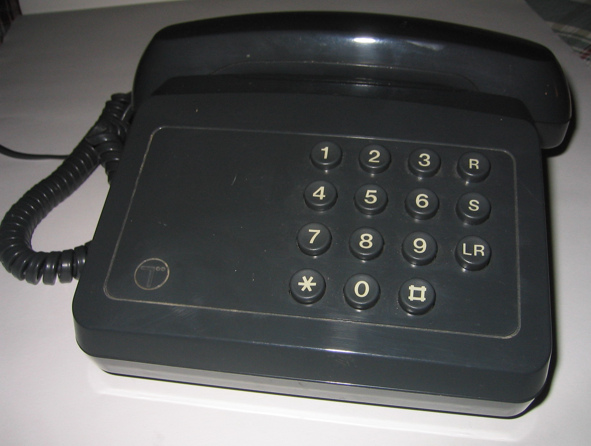
Tribune
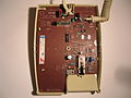
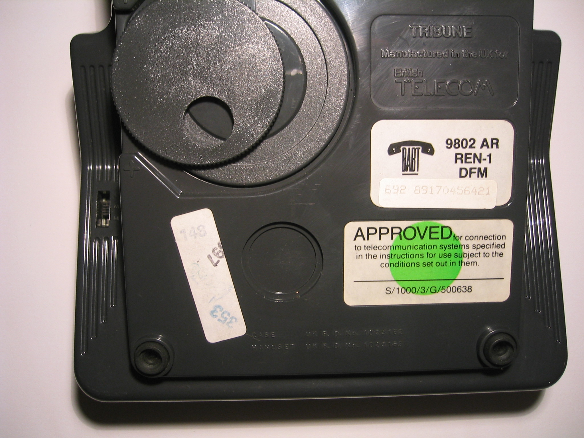
This telephone was able to operate on both loop disconnect (pulse) and MF4 (tone) dialling. The method was chosen by a switch on the base, as shown in the photograph. It was introduced in the 1980s as a basic telephone and was the last model with a mechanical bell. The volume control was the ultimate in simplicity: a plastic disc with a hole in it which could be rotated to cover over the sounder holes by a varying amount.
-
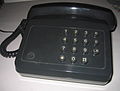
GPO Tribune Blue
-
GPO Tribune Blue base. Note switch on the left hand side to change from Loop Disconnect to MF4. Also shows the wheel which is a crude method of adjusting the ringing volume
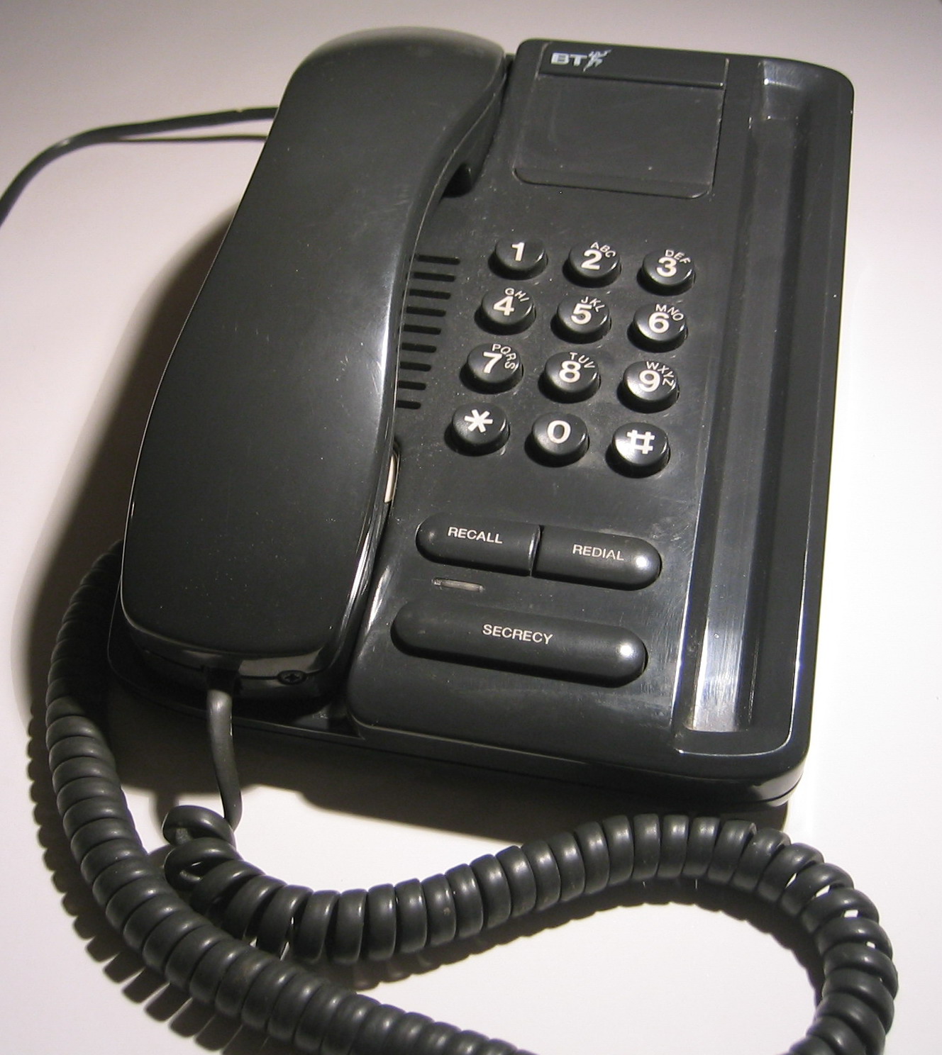
Relate and React
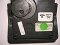
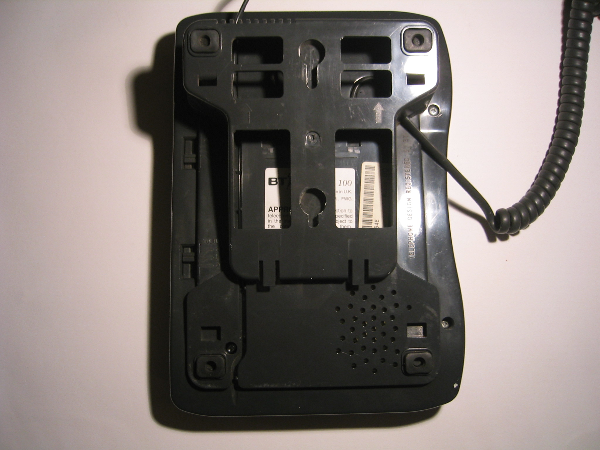
These telephones are able to operate on both loop-disconnect (pulse) and MF4 (tone) and a switch on the base of the telephone chooses the method. The volume of the ringer could also be changed to High, Low or Off. The Relate is shown, the React has a squarer styling, without the pen-holder tray. Note also that on the underside there is a mount that can be fitted in two positions. One makes it a desk telephone and mounting it the other way round turns it into a wall telephone - very ingenious.
-
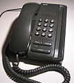
GPO Relate 100 Blue
-
GPO Relate 100 Blue base. Note switch on the left hand side to change from Loop Disconnect to MF4 and also the ringer volume
Prelude
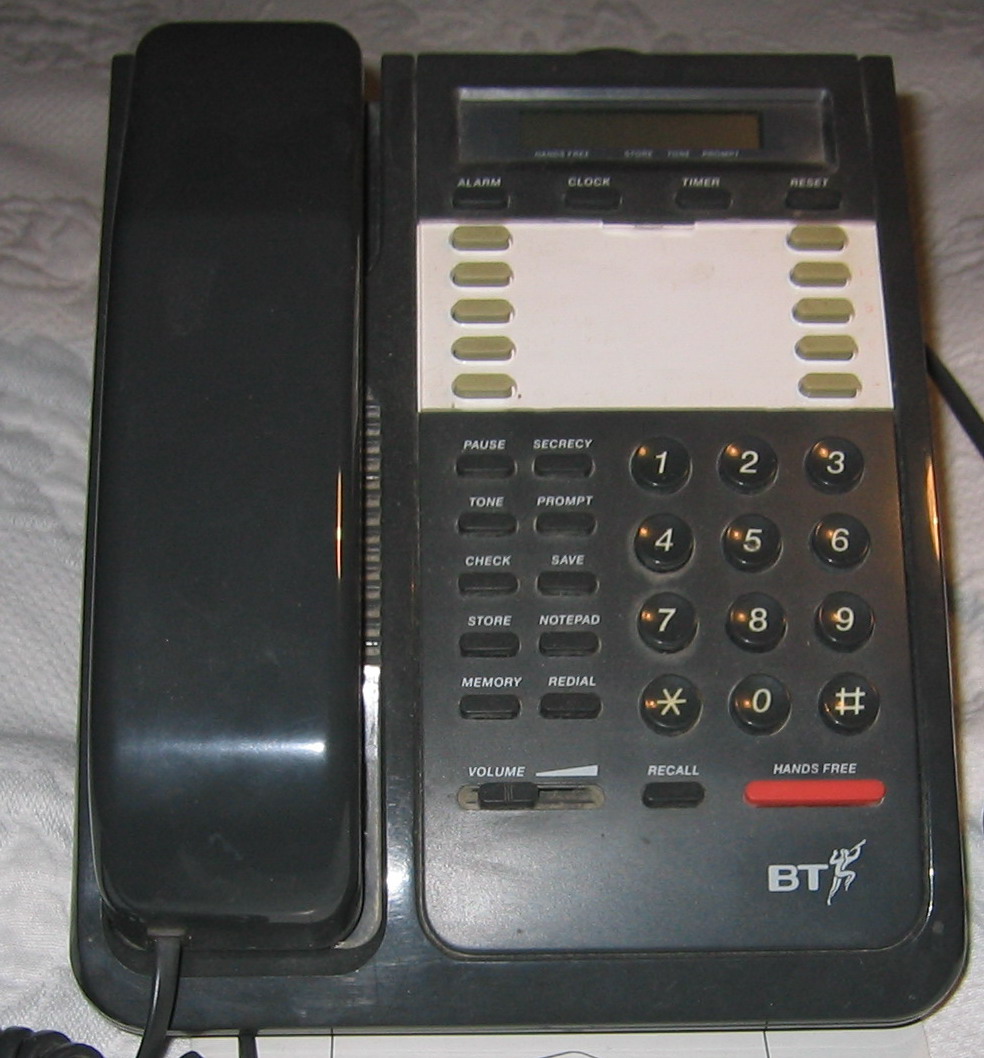
One of the first telephones with built in loudspeaking capability. This telephone is not a domestic instrument but one of many designed for use on early electronic office systems. Note the ten direct-dial extension buttons.
-
GPO Prelude
External links
Categories:- Telecommunications equipment
- Telephony equipment
-


Wikimedia Foundation. 2010.