- OMTROLL
-
OMTROLL[1] basically is an Object-oriented modeling idea that has been formulated by combining the traditional Object Modelling Approaches(OMT) and the formal specifications of the TROLL language. OMTROLL was basically created so as to: exploit the practical analysis of OMT, eliminate the ambiguity and vagueness in OMT, and to exploit the formal system specifications provided bt TROLL.
Contents
Brief History
There has been considerable research going on, over the past years in the areas of Object Oriented Analysis and Object Oriented formal specifications. OMT life cycle analysis concentrates mainly in software development practice whereas TROLL,[2] oblog, FOOPS etc. are formal languages developed mainly with a mathematical background, having their roots in logic, algebra, set theory etc. The need to combine these two areas of Object Oriented approaches into a single formalism, is because the OO analysis methods do not reach the level of ordering achieved by the formal specification languages. These formal languages are being used research and applied in various software development projects.
TROLL vs OMT
TROLL is a formal language used to specify an object system. It is more concerned with the dynamic behaviour of an object over time. In TROLL, an object can change in a discrete manner due to certain events. The object can be created by the occurrence of certain events (birth event) and ended by the occurrence of certain other events(death events). The current state of an object is specified by it attributes. A role is the part played by an object temporarily and a specialization is the role played by it permanently. Objects can also be components of other objects-composite objects, or may be connected by means of some interaction. Also views can be defined that contain only certain information of the current state of the object. Now the central idea of TROLL is to interpret such an object as a set of observable sequential processes. So the object lifetime would be a series of events occurring on the object, and the current state of the object would depend on all the events that have occurred on it in the past.
OMT model of a system consists of: (a)The Object model represents the structure of objects in the system, similar to an ER diagram. (b)The Dynamic model shows the control aspects of the system like time, interactions between objects etc. (c)The Functional model defines the meaning of operations and how values are changed due to interactions in the system. Now the drawback of OMT is that the various operations on the object are spread over into 3 different models, causing a relationship among the entities in different models (like the dynamic and object model)to become abstract. Also the communication can only be represented in the functional model.
Stages in System Analysis
System analysis basically consists of following stages:
a)Structure analysis: gives the details of the hierarchical and organizational structure of the system.
b)Task analysis: Like its name, it determines which task is done, when it is done and who did it. It processes the input and shows how the output is obtained.
c)Communication analysis: show how relationships are established between operations, and class interactions.
d)Document analysis: describes the documents and rules that are used in the system.
e)Process analysis: gives information about the execution of operations.
Diagrammatic Representations in OMTROLL
Behaviour Diagram
These are also called State Transition Diagrams. They define the behaviour of the system. They are usually modelled in the initial stages. There are 2 main states- initial and final state. The transition from one state to another is based on conditions/actions. The behavioural diagram is further refined to details.
Community Model
The community model gives an overview of all the object classes and the concurrent objects of the system. An Object class encapsulates the data that describes objects of the same structure and behaviour. A complex object class can have single or multiple components.
A complex object class contains many objects. An object can perform various actions at a particular time, but cannot have a concurrency within itself. Also an object class that isn’t involved in any sort of relationship(component/specialization) is called an independent object class.
Object Class Declaration Diagram
This diagram shows the object attributes and their domains, and optional parameters. Object attributes can be :
i)Object-valued: these are the attributes that behave like a pointer/ reference to the object. These may further be Single or multiple object-valued attributes. Constructors like: set, list, bag, map can be used with multiple object-valued attributes.
ii)Data-valued
A community diagram along with its corresponding object class diagram forms the structural part of a system.
Communication diagram
As its name suggests, it diagrammatically represents the communication between objects of the system. OMT doesn't support interaction between objects, so the communication diagram is introduced in OMTROLL. The boxes represent the class and inner boxes refer to events. These event boxes are connected by means of arrows. A precondition can be assigned to events. Communication within a complex object class is also possible.Communication can be of 2 types-a complex object communicating with its components, or concurrent objects communicate with each other.
Data type diagram
For specifying attributes and actions we use user-defined data types (nat,int(integer), real,bool(boolean), string,date etc.). Using these types we construct new data types like lists, records, enumeration etc.
Specification in OMTROLL
There are a set of steps that are used in the designing process in OMTROLL. There are a number of rules associated with each such step.
Notation
The notations used are object class, attribute, component, action,etc. with names given to each of them.
Rules followed in OMTROLL
The rules associated with each step are given below:
Step 0: Determining the specification notation.
Rule 0.1:
- language used for specification.
- Wether to use capital or samall case.
- Increasing readability of identifiers.
Example: For specifying a system for a Shopping Mall
- The English language is used for specification
- Object classes are specified using uppercase
- Actions and attributes are specified in lowercase
- Underscores can be used to increase readability of long identifiers
- Object instances in the object class start with upper case.
Now we have a specification of the system-a platform to build on. In the next stage, we start out with the structural analysis of the system. We identify the object classes, their attributes, and the relationship between these object classes. This is done by means of a Community diagram.
Step 1: Identify object classes.
Rule 1.1: Finding identifier for the object class. The identifier can be:
- Can be the domain.
- Can be the entities stored in the system or which represent information.
- Can be entities that produce, change or analyse information.
Rule 1.2: Defining what an object is.
- It should be an entity with several properties describable by attributes.
- It should perform actions that cause it to change state.
- It should be identifiable; even though it could be imaginary in the real world.
Rule 1.3: An object class should encapsulate a set of similar objects.
Rule 1.4: Differentiate between users of the system. There can be 2 types of users:
- User of the system as physical person: In this case the system is specified keeping in mind the functions a user interacting with the system would need. Such a case is represented as a object class as a separate entity from the system.
- User data stored in the system: In this case the user information, as well as the operations to change this information is specified. They are represented as a component of the system.
In this stage all the object classes and their actions and attributes have been fixed. In the next stage the relationship between these classes is determined.
Step 2: Establish relationship between classes.
Rule 2.1: The relationships that exist between classes are:
- Component relationship between an aggregated object class and its components.
- Specialization relationship between a object class and its sub-classes.
- Concurrency between independent classes.
A sub-object class is also a component
Rule 2.2: The component should have the following characteristics:
- Can be identified only in the context of a parent object.
- Depends on its parent object.
- May be restricted in the context of the parent object.
- Contains certain aspects of the parent object.
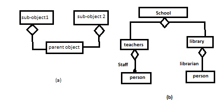
Rule 2.3: Establishing a component relationship. A component relationship is exclusive, static, transitive and antisymmetric. All actions and attributes of a object class are a part of its parent class. The component relationship must have an identifier that uniquely identifies the components. Shared components cannot be modelled. But an object component can be reused. Figure 7 (a) is not modelled in OMTROLL, but (b) can occur.
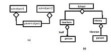 Figure 7: diagrammatic representation of permissible and non-permissible components
Rule 2.4: Establishing specialization relationships. The specialization relationships would have the following characteristics:
- An object behaves like another object, but it has unique properties and actions.
- All specialized objects are objects of a super class.
Rule 2.5: Determining distribution. All the classes that aren’t in a component or specialization relationship are concurrent. Nodes are used to specify such independent classes. The characteristics of a node are:
- They are neither components or specializations of other classes.
- There are only communication relations between them.
- Their existence depends on the existence of the system.
- They can exist independently.
Rule 2.6: Each node gets its own identifier. Each node should be determined, as to whether it is necessary system component or if node is identifiable with the system.
Now the overall structure has been fixed. Now in the next step the attributes and actions are specified.
Step 3: Specifying object class signature
Rule 3.1: Declaring the attributes. The object properties in the real world are specified by its attributes. To find the appropriate attributes of an object in its domain the following rules can be applied:
- Adjectives assigned to an object in the system could be possible attributes.
- Entities that are not objects could be attributes.
- The attributes need to hold for the specified domain.
Rule 3.2: Attribute features:
- Constant attributes have a constant value that remains fixed during th lifetime of the object.
- Derived attributes are computed from the base objects.
- Hidden attributes are only visible in the object class it is defined in.
- Optional attributes can be assigned in later stages.
- Initialized attributes have fixed initial value.
Rule 3.3: Data type declaration. The data types can be:
- Predefined like int, real, bool etc.
- Type constructors like set, list, record etc.
- Each object class specification implicitly determines identification data type. This data type is denoted by <ident>.
- Type constructor must not contain cycles.
- Each sort used for construction must be specified.
Rule 3.4: If an object-valued attribute of Class 1 is present in Class 2, the actions and attributes of Class 1 cannot be visible to Class 2.
Rule 3.5: Objects communicate through actions. Each action symbol is specified by a name and its parameters(optional).
Rule 3.6: Specifying birth and death events. An object class has at least 1 birth event. Specialized classes have no birth or death event, but they inherit their parent class’ birth and death events. Birth actions are preceded by a ‘+’ and death actions by a ‘*’. The birth event needs to have parameters that assign values to non-derived attributes.
Rule 3.7 : All state changing actions are specified.
Rule 3.8: Every action has a signature, which consists of an input parameter-set by caller, or a parameter is an output parameter which is given to the caller by the action. A (!) mark indicates an output parameter.
In the next stage the local behaviour of an object is defined. This is so as to be able to find out if there are existing dependencies between the actions.
Step 4: Specifying local object class behaviour.
Rule 4.1: For every object class that have objects whose behaviour can be described as a sequential process, a behaviour diagram is specified. This diagram puts a strict ordering of the actions on the object. Behaviour diagram though, unlike the remaining diagrams, are not directly translated to TROLL. They are only a means to visualize behaviour patterns. Behaviour diagrams can be specified at different levels of abstraction, and the more detailed the behavioural diagram, the more information of the stated behaviour can be translated to textual specification.
The last stage determines the communication between object classes. Objects communicate by action calling. In TROLL action calling is directed and synchronous.
Step 5: Determining communication model.
Rule 5.1: There are 2 kinds of communication:
- Communication between complex object and its components.
- Communication between concurrent objects.
These 2 types are shown in Figure 8.
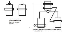 Figure 8: types of communication between object classes
Rule 5.2: Specifying the communication forces forces the designer to synchronize the actions between object classes.Rule 5.3: Communication patterns in complex object classes are independent from specific instances.
References
- ^ Ralf Jungclaus, Roel J. Wieringa, Peter Hartel, Gunter Saake, Thorsten Hartmann. "Combining TROLL with th Object Modelling Technique" (PDF). http://citeseerx.ist.psu.edu/viewdoc/summary?doi=10.1.1.49.3051.
- ^ "TROLL overview". http://www.intex.com/troll/overview.html.
External links
Categories:

Wikimedia Foundation. 2010.