- Multiway switching
-
In building wiring, multiway switching is interconnection of two or more light switches to control lighting from more than one location. This allows lighting in a hallway or stairwell to be controlled from either end.
Contents
Three-way and four-way
This article follows American usage. Readers in the UK should read "two-way" for the American "three-way" and "intermediate" or "crossover" switch for the American "four-way".[1][2]
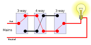
Three-way and four-way switches make it possible to control a light from multiple locations, such as the top and bottom of a stairway, or either end of a long hallway. These switches are externally similar to single-pole switches, but have extra connections which allow two circuits to be controlled. Toggling the switch disconnects one circuit and connects the other.
Electrically, a three-way switch is a single-pole, double-throw (SPDT) switch. By connecting two of these switches together, toggling either switch changes the state of the light from off to on, or on to off. A four-way switch has two pairs of terminals which it connects either straight through, or crossed over. By connecting one or more four-way switches in-line with three-way switches at either end, the light can be controlled from three or more locations. Toggling any switch changes the state of the light from off to on, or on to off.
Two locations
Switching a load on or off from two locations (for instance, turning a light on or off from either end of a flight of stairs) requires two SPDT switches. There are two basic methods or systems of wiring to achieve this.
Traveler system
The traveler system may also be called the "Common system", due to the line and load of the system being connected to the common terminal of their respective three-way switch.
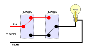
In the traveler system, the line hot is fed into the common terminal of one of the switches; the switches are then connected by a wire pair called "Travelers", as shown, and the lamp is connected to common of a second switch. This method requires two wires between the switches.
Using the traveler system, there are four possible combinations of switch positions: two with the light on and two with the light off.
-
Off On 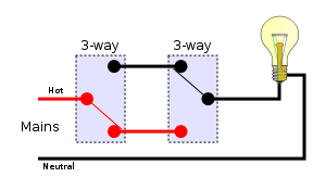
Alternative system
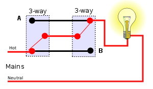 The "California 3-way" or "Coast 3-way" connection never connects the lamp socket shell to the live terminal. An additional lamp can be connected at A as a pilot lamp or for a long corridor. A receptacle can be connected at B since that terminal is always live. For example, in an outbuilding, this would save one wire, but the more common traveler system needs one less wire in the first place, so there is no actual saving unless an additional wire was needed anyway due to the position of the lamps.
The alternative system is also known as the California 3-way or the coast 3-way. It is a method of wiring using four conductors and two three-way switches. It allows for a hot receptacle at both ends of the circuit as well as switched light outlets on both ends. Its main benefit is that it saves on conductors when the wire to the light is located near the wire from the mains, since they are both in the same switch box. It can also light a lamp (or a second lamp) that is near the second switch box without having to pass an extra wire (with the standard system an extra wire would be needed). Its main drawback is that it is wired up to the 3-way switches in a non-standard manner that can cause confusion and mis-wiring for anyone who follows the initial installer. When wired correctly, it does not pose an electrical code violation as the neutral is never switched. While this method requires three wires between the switches, it also gives the advantage of allowing loads at both ends of the switched circuit to be controlled from either end.
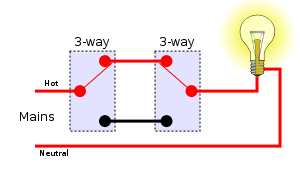
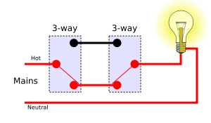
The alternative system is to join the three terminals of one switch to the corresponding terminals on the other switch. The incoming supply and the lamp are connected as shown. This method requires three wires between the switches.
The alternative system should not be confused with the Carter system. The alternative system is legal, but can be confusing.
Carter system
 The Carter system is not recommended.
The Carter system was a method of wiring 3-way switches in the era of knob and tube wiring. Two of the four switch position combinations are dangerous, and this wiring method has been prohibited by the National Electrical Code since 1923.
In the Carter system, the incoming live (energized) and neutral wires are connected to the traveler screws of both 3-way switches, and the lamp is connected between the common screws of the two switches. If both switches are flipped to hot or both are flipped to neutral, there is no light; but if they are switched to opposite positions, there is light. The advantage of this method is that it uses just one wire to the light from each switch, having a hot and neutral in both switches.
The major problem with this method is that two switch combinations apply the live (hot) wire to the outer shell of the light socket, presenting a dangerous electrical shock hazard. The lampholder shell may still be energized even with the light off, which poses a risk when changing a bulb. This method is prohibited in building wiring where the neutral and live conductors must be distinguished.
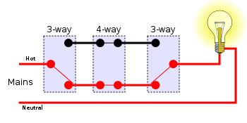
More than two locations
For more than two locations, two of the interconnecting wires must be passed through an intermediate switch, wired to swap them over. Any number of intermediate switches can be inserted, allowing for any number of locations. This requires two wires along the sequence of switches.
Traveler system
Using the traveler system, there are eight possible combinations of switch positions: four with the light on and four with the light off. N.B. This diagram also uses the American electrical wiring names.
-
Off On 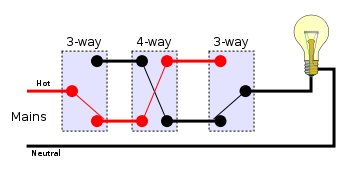
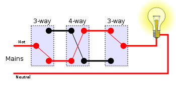
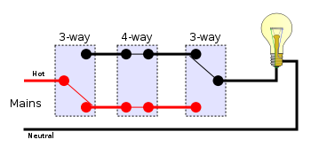
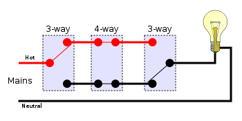
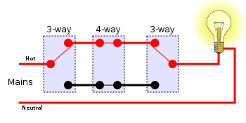
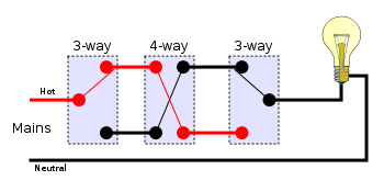
As mentioned above, the above circuit can be extended by using multiple 4-way switches between the 3-way switches to extend switching ability to any number of locations.
References
Further reading
- Richard Day Wiring Multi Switches, page 85 and following, in Popular Science Jan 1987, Vol. 230, No. 1 ISSN 0161-7370
Categories: -


Wikimedia Foundation. 2010.